Spreaders for efficient tank loading and unloading

A high-efficiency, tank-body technology, applied in the directions of transportation and packaging, load hanging components, etc., can solve the problems of long time-consuming and incapable of automatic loading and unloading of ceramic wine cans, achieve efficient automatic loading and unloading, improve stability, Simple and convenient operation

Active Publication Date: 2020-12-18
重庆安都陶瓷有限公司
View PDF5 Cites 0 Cited by
  • Summary
  • Abstract
  • Description
  • Claims
  • Application Information

AI Technical Summary

Problems solved by technology

[0003] The invention provides a sling for efficient loading and unloading of tanks to solve the problem that the existing lifting structure cannot automatically load and unload, which makes loading and unloading of ceramic wine tanks take a long time

Method used


Image

  • Spreaders for efficient tank loading and unloading
  • Spreaders for efficient tank loading and unloading
  • Spreaders for efficient tank loading and unloading

Examples


Embodiment 1

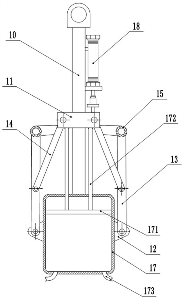
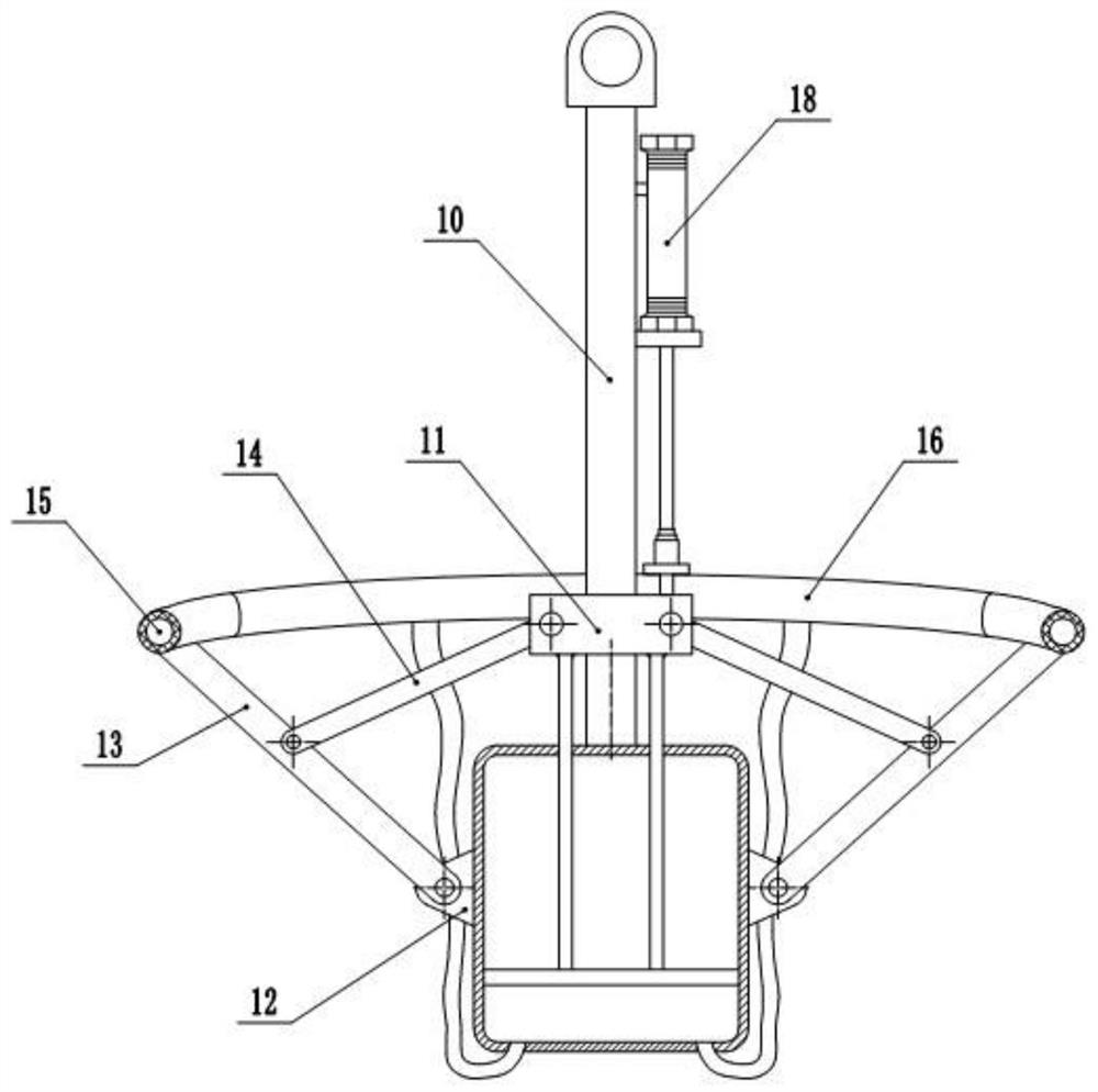
[0033] Embodiment 1 is basically as attached figure 1 and figure 2 Shown:

[0034] The lifting tool for efficiently loading and unloading tanks includes a vertical shaft 10, a sliding seat 11 and a cylinder body 17 with a closed bottom. A pull ring is fixed on the top of the vertical shaft 10, and the hook on the electric hoist can be directly worn on the pull ring. The sliding seat 11 is slidably connected on the vertical shaft 10, and the cylinder body 17 is fixed on the bottom of the vertical shaft 10, and a plurality of connection seats 12 are fixed on the side wall of the cylinder body 17, and the connection seats 12 are evenly distributed along the circumference of the cylinder body 17, A support rod 13 is hinged on the connecting seat 12, a pull rod 14 is hinged between the support rod 13 and the sliding seat 11, and a plurality of mounting grooves are arranged on the outer circumference of the sliding seat 11, and the end of the pull rod 14 away from the support rod ...

Embodiment 2

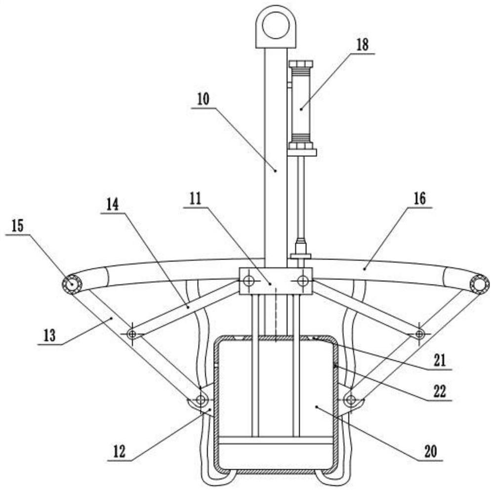
[0039] Embodiment 2 is basically as attached image 3 Shown:

[0040] The difference from Embodiment 1 is that the top of the cylinder body 17 is closed, and the piston 171 separates the cylinder body 17 into a closed upper cavity 20 and a lower cavity, and the top of the cylinder body 17 is provided with a positioning hole for the connecting rod 172 to slide. The top of the body 17 is provided with a plurality of air outlet holes 21 uniformly distributed along the vertical axis 10 circumferentially. The upper part is provided with the air inlet 22 that communicates with the upper chamber 20, and the air inlet 22 is provided with an air intake check valve. When the volume of the upper chamber 20 increases, the air pressure in the upper chamber 20 decreases, and the air intake When the one-way valve is opened, outside air enters the upper chamber 20, and when the volume in the upper chamber 20 decreases, the air pressure in the upper chamber 20 increases, the air outlet check ...


PUM


Abstract

The invention relates to the technical field of hoisting equipment, and particularly discloses a lifting tool for efficiently loading and unloading tank bodies. The lifting tool comprises a vertical shaft, a sliding seat and a cylinder block with a sealed bottom, wherein the sliding seat is vertically and slidably connected to the vertical shaft, the cylinder body is fixed at the bottom of the vertical shaft, a plurality of supporting rods are hinged to the circumferential direction of the cylinder body, and a pull rod is hinged between the supporting rod and the sliding seat; rubber pipes arefixed at the free end of the supporting rod, and an elastic pipe is connected between the adjacent rubber pipes; and a piston is slidably connected in the cylinder body, a connecting rod is fixed between the sliding seat and the piston, a gas supply pipe is connected between the bottom of the cylinder body and each elastic pipe, and a driving part for driving the sliding seat to move up and downis further arranged on the vertical shaft. By adopting the lifting tool, efficient and automatic loading and unloading of ceramic wine tanks can be carried out, and the loading and unloading efficiency are improved.

Description

technical field [0001] The invention relates to the technical field of hoisting equipment, in particular to a hoist for efficiently loading and unloading tank bodies. Background technique [0002] Most of the liquor manufacturers in our country use ceramic wine tanks to store wine; It is broken and has a relatively smooth appearance, so it is difficult to carry. The existing production process usually adopts the method of hoisting, and the existing hoisting structure is realized by binding a wooden stick at the bottom of the pull rope. When using, the operator needs to put the wooden stick Put the stick into the tank after it is vertical, and then tighten the pull rope to make the stick horizontal. It takes a long time and requires a certain amount of manpower. In addition, due to the small contact area between the two ends of the wooden rod and the inner wall of the tank, the support of the hoisting structure to the inner wall of the tank is not stable enough during the ho...

Claims


Application Information

Patent Timeline
Patent Type & Authority Patents(China)
IPC IPC(8): B66C1/42
CPCB66C1/427
Inventor 袁宗坤
Owner 重庆安都陶瓷有限公司
Why Eureka
Try Eureka