Common rail type optical fiber drawing device and drawing method thereof
A common rail, wire drawing technology, applied in glass manufacturing equipment, manufacturing tools, etc., can solve the problem of adsorption of impurities on the surface of optical fiber preforms, and achieve the effects of increased weight, uniform and symmetrical structure, and increased cross-sectional area.
- Summary
- Abstract
- Description
- Claims
- Application Information
AI Technical Summary
Problems solved by technology
Method used
Image
Examples
Embodiment 1
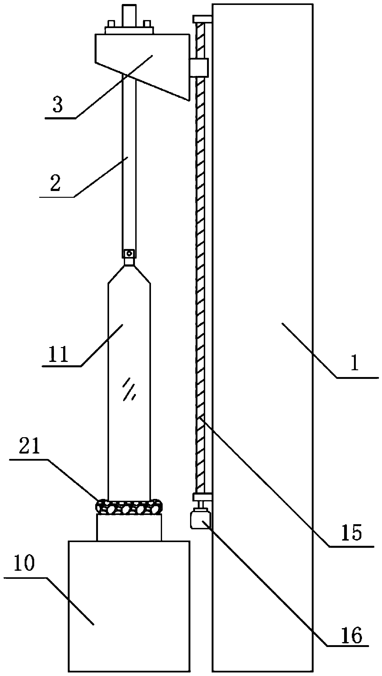
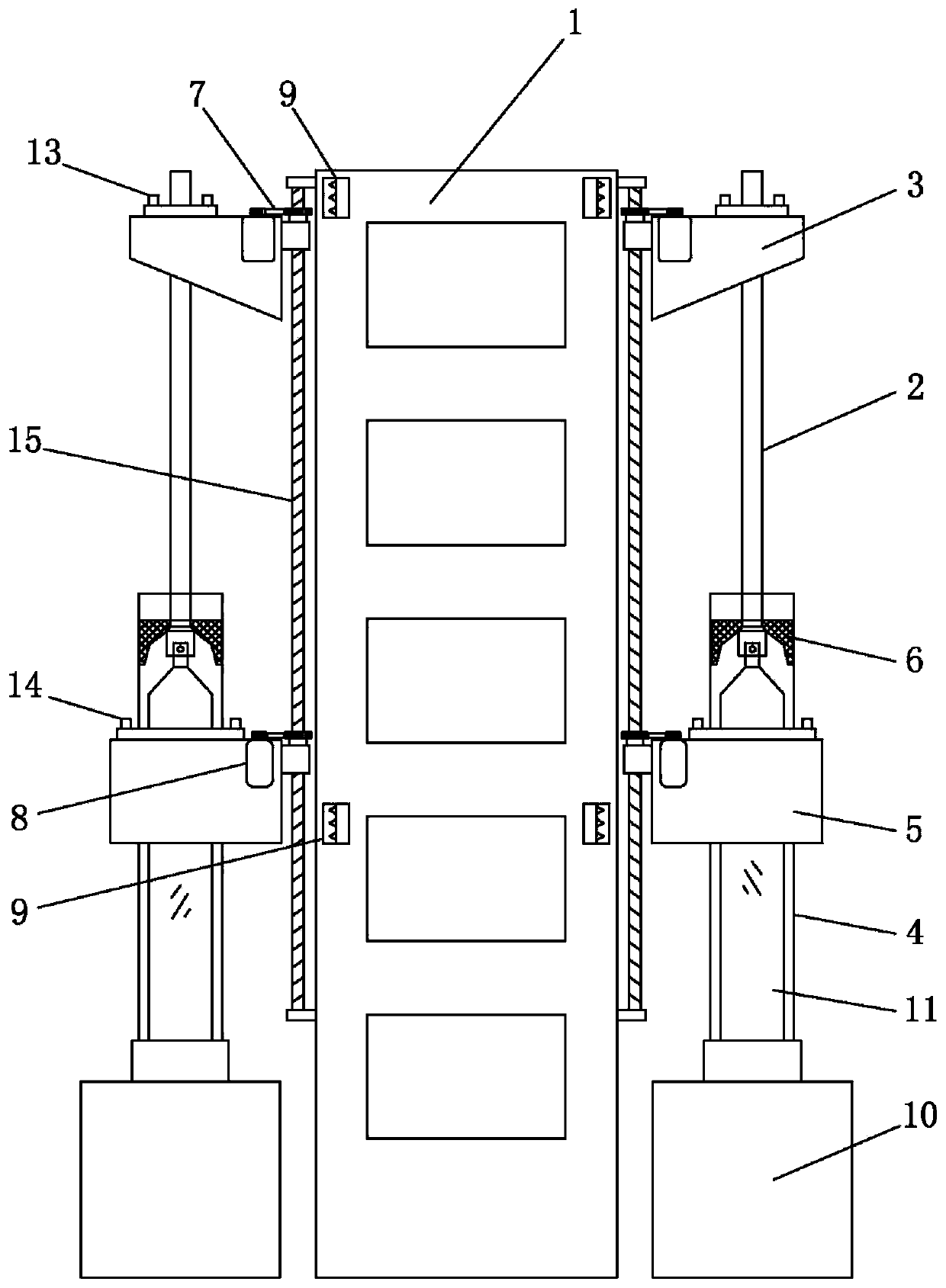
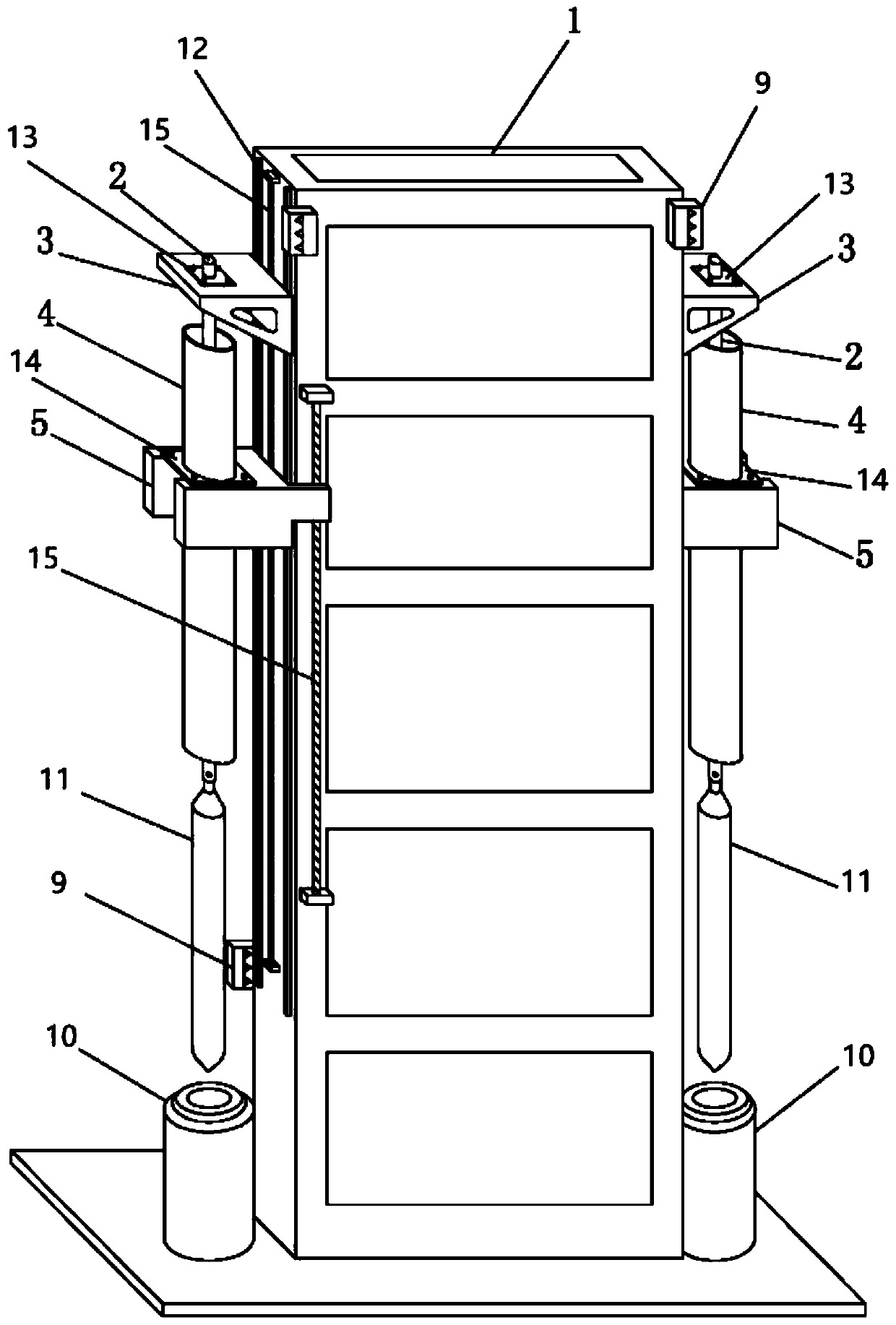
[0051] see figure 2 , image 3 , Figure 4 and Figure 5 As shown, the embodiment of the present invention provides a common rail optical fiber drawing device, including:
[0052] The bar beam tower 1 is fixed with a guide rail 12 on the side wall of the bar beam tower 1. There are two guide rails 12, and the two guide rails 12 are parallel to each other and spaced apart on the side wall of the bar beam tower 1. Set, the guide rail 12 extends along the height direction of the bar feeding beam tower 1.
[0053] Send the rod support part 3, the bottom of the rod support part 3 is provided with the rod 2;
[0054] Sealing cylinder supporting part 5, this sealing cylinder supporting part 5 is positioned at the below that sends rod supporting part 3, and sealing cylinder supporting part 5 and sending rod supporting part 3 are slidably connected on the same guide rail 12. The below of sealing cylinder supporting part 5 is provided with sealing cylinder 4, sends rod 2 and seali...
Embodiment 2
[0062] see figure 2 , image 3 , Figure 4 and Figure 5 As shown, the embodiment of the present invention provides a common rail optical fiber drawing device. Compared with Embodiment 1, the difference between this embodiment is that the rod feeding beam tower 1 of this embodiment is preferably but not limited to a rectangular cross section. The steel frame structure, the specific cross-sectional structure of the rod beam tower 1 can also be selected by those skilled in the art as a triangular or regular polygonal structure. On the side walls parallel to each other on the bar beam tower 1, fix the guide rail 12 respectively, adopt the same mode as embodiment 1 to set the bar support part 3, the sealing cylinder support part 5, the bar bar 2, The sealing cylinder 3, the lifting mechanism and the high-temperature furnace 10 can realize that multiple optical fiber drawing production lines can be expanded on the rod feeding beam tower 1, and then realize the modular layout of...
Embodiment 3
[0064] see figure 2 , Figure 7 and Figure 9 As shown, the embodiment of the present invention provides a common rail optical fiber drawing device. Compared with Embodiment 1, the difference between this embodiment is that the rod feeding rod support part 3 of the embodiment of the present invention is provided with a rod feeding rod leveling structure 13. The rod feeding rod 2 is fixed on the rod feeding rod leveling structure 13, the rod feeding rod leveling structure 13 is connected with the rod feeding rod supporting part 3 by thread, and the rod feeding rod leveling structure 13 and the rod feeding rod supporting part are adjusted The relative position between 3 can adjust the setting position of the rod feeding rod 2, ensuring that the rod feeding rod 2, the sealing cylinder 4 and the high temperature furnace 10 are coaxial. The sealing cylinder support part 5 is provided with a sealing cylinder leveling structure 14, and the sealing cylinder 4 is fixed on the sealin...
PUM
 Abstract
Description
Claims
Application Information
 - R&D
- Intellectual Property
- Life Sciences
- Materials
- Tech Scout
- Unparalleled Data Quality
- Higher Quality Content
- 60% Fewer Hallucinations
Browse by: Latest US Patents, China's latest patents, Technical Efficacy Thesaurus, Application Domain, Technology Topic, Popular Technical Reports.
© 2025 PatSnap. All rights reserved.Legal|Privacy policy|Modern Slavery Act Transparency Statement|Sitemap|About US| Contact US: help@patsnap.com


