A common rail optical fiber drawing device and drawing method thereof

A common rail and wire-drawing technology, which is applied in the direction of manufacturing tools and glass manufacturing equipment, can solve the problems of adsorption of impurities on the surface of optical fiber preforms, and achieve the effects of improving equipment production stability, stable operation, and improving efficiency

Active Publication Date: 2022-04-29
FENGHUO COMM SCI & TECH CO LTD +1
View PDF7 Cites 0 Cited by
  • Summary
  • Abstract
  • Description
  • Claims
  • Application Information

AI Technical Summary

Problems solved by technology

[0006] The purpose of the present invention is to overcome the disadvantages of the optical fiber drawing tower rod feeding mechanism in the above-mentioned background technology, which only has a set of rod feeding transmission system, which is only responsible for feeding the optical fiber preform, and cannot solve the problem of adsorption of impurities on the surface of the exposed optical fiber preform , providing a common rail optical fiber drawing device and drawing method thereof

Method used


Image

  • A common rail optical fiber drawing device and drawing method thereof
  • A common rail optical fiber drawing device and drawing method thereof
  • A common rail optical fiber drawing device and drawing method thereof

Examples


Embodiment 1

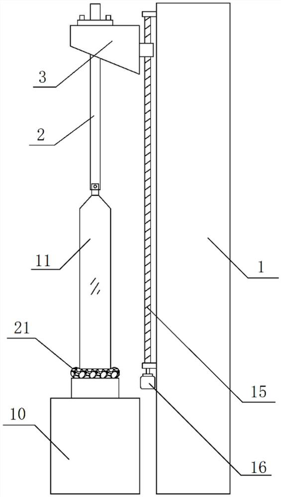
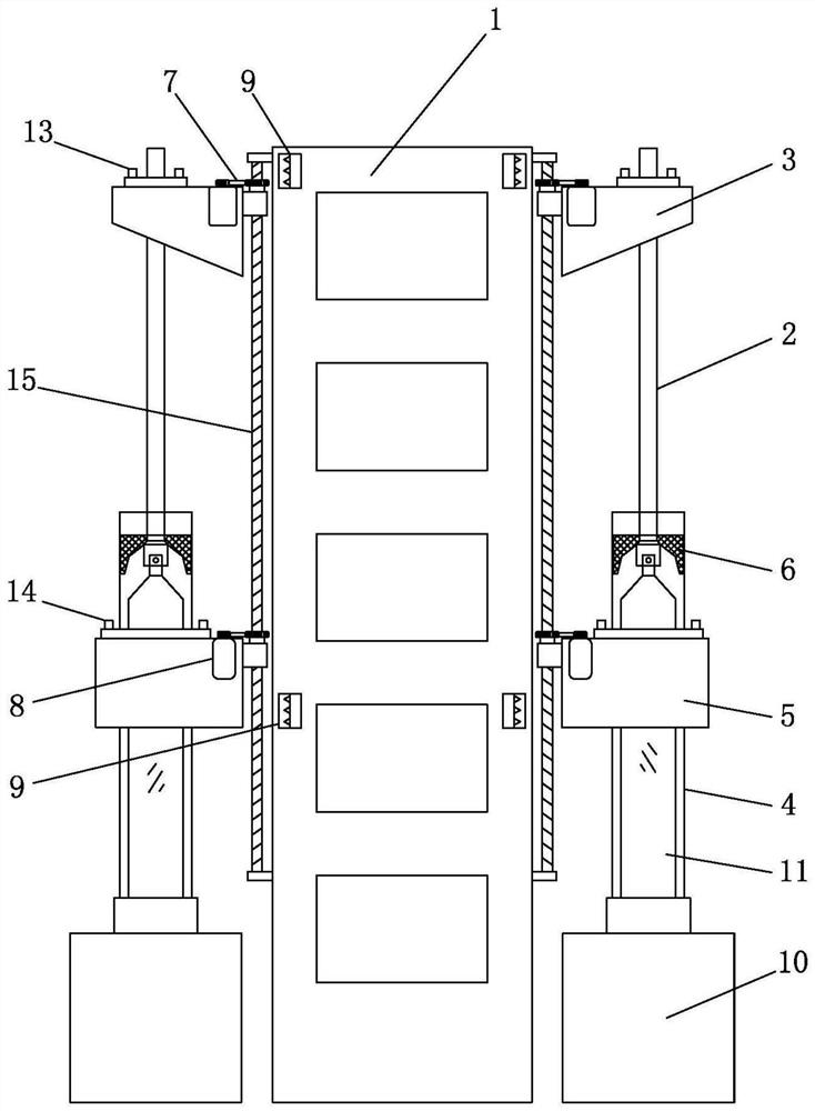
[0051] see figure 2 , image 3 , Figure 4 with Figure 5 As shown, the embodiment of the present invention provides a common rail optical fiber drawing device, including:

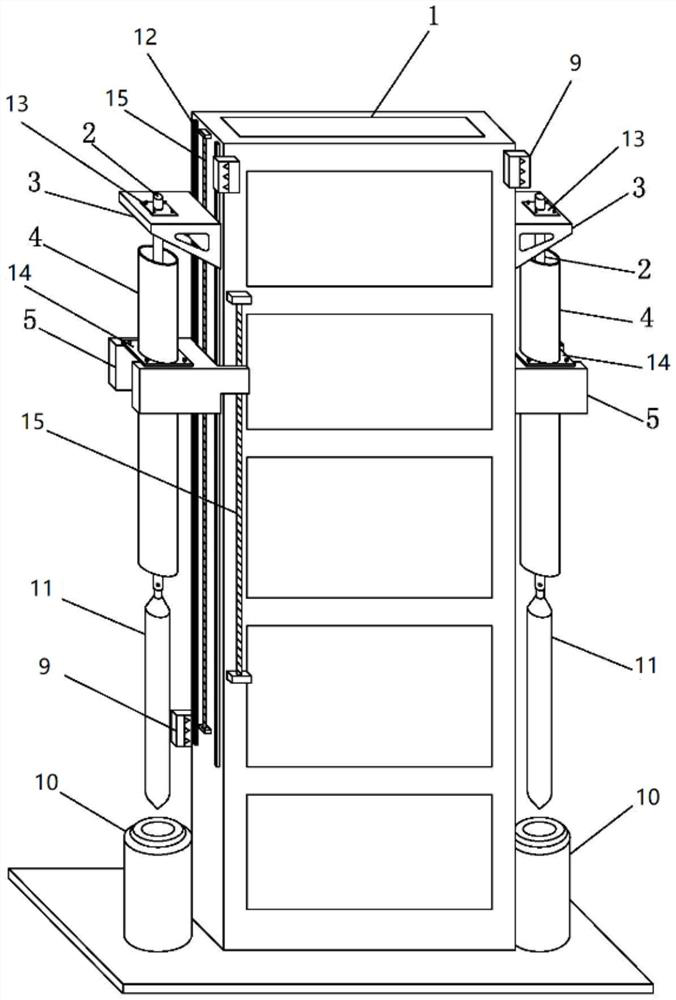
[0052] The bar beam tower 1 is fixed with a guide rail 12 on the side wall of the bar beam tower 1. There are two guide rails 12, and the two guide rails 12 are parallel to each other and spaced apart on the side wall of the bar beam tower 1. Set, the guide rail 12 extends along the height direction of the bar feeding beam tower 1.

[0053] Send the rod support part 3, the bottom of the rod support part 3 is provided with the rod 2;

[0054] The sealing cylinder supporting part 5, the sealing cylinder supporting part 5 is located below the rod feeding rod supporting part 3, and the sealing cylinder supporting part 5 and the rod feeding rod supporting part 3 are slidably connected on the same guide rail 12. A sealing cylinder 4 is arranged below the sealing cylinder supporting part 5, and the feeding ...

Embodiment 2

[0062] see figure 2 , image 3 , Figure 4 with Figure 5 As shown, the embodiment of the present invention provides a common rail optical fiber drawing device. Compared with Embodiment 1, the difference between this embodiment is that the rod feeding beam tower 1 of this embodiment is preferably but not limited to a rectangular cross section. The steel frame structure, the specific cross-sectional structure of the rod beam tower 1 can also be selected by those skilled in the art as a triangular or regular polygonal structure. Fix guide rails 12 respectively on the side walls parallel to each other on the rod beam tower 1, adopt the same method as embodiment 1 to set the rod support part 3, the sealing cylinder support part 5, the rod rod 2, The sealing cylinder 3, the lifting mechanism and the high-temperature furnace 10 can realize that multiple optical fiber drawing production lines can be expanded on the rod feeding beam tower 1, and then realize the modular layout of ...

Embodiment 3

[0064] see figure 2 , Figure 7 with Figure 9 As shown, the embodiment of the present invention provides a common rail optical fiber drawing device. Compared with Embodiment 1, the difference between this embodiment is that the rod feeding rod support part 3 of the embodiment of the present invention is provided with a rod feeding rod leveling structure 13. The rod feeding rod 2 is fixed on the rod feeding rod leveling structure 13, the rod feeding rod leveling structure 13 is connected with the rod feeding rod supporting part 3 by thread, and the rod feeding rod leveling structure 13 and the rod feeding rod supporting part are adjusted The relative position between 3 can adjust the setting position of the rod feeding rod 2, ensuring that the rod feeding rod 2, the sealing cylinder 4 and the high temperature furnace 10 are coaxial. The sealing cylinder support part 5 is provided with a sealing cylinder leveling structure 14, the sealing cylinder 4 is fixed on the sealing c...


PUM


Abstract

The invention discloses a common-rail optical fiber drawing device and a drawing method thereof, belonging to the technical field of optical fiber production equipment. It includes: the bar feeding beam tower, the side wall of the bar feeding beam tower is fixed with a guide rail, and the guide rail extends along the height direction of the bar feeding beam tower; rod; the sealing cylinder support part, the sealing cylinder support part is located below the rod feeding support part, and the sealing cylinder support part and the rod feeding support part are slidably connected on the same guide rail, and the sealing cylinder is provided under the sealing cylinder support part, The rod feeding rod and the sealing cylinder are coaxial; the lifting mechanism is arranged on the side wall of the rod feeding beam tower, and the lifting mechanism is used to drive the rod feeding support part and the sealing cylinder support part to move up and down on the guide rail. The invention adopts a sealing cylinder and a sealing ring, can provide a clean sealing environment for wire drawing production, and solves the problem of absorbing impurities on the surface of the optical fiber preformed rod.

Description

technical field [0001] The invention relates to the technical field of optical fiber drawing preparation, in particular to a common rail optical fiber drawing device and a drawing method thereof. Background technique [0002] With the gradual deepening of information Internet construction, mobile communication has now entered the era of popularization of 4G communication, and the multi-dimensional big data market demand for the interconnection of everything and human-computer interaction has promoted the birth of 5G. As the carrier of information transmission, optical fiber will continue to increase market demand in the construction of 4G and 5G, and the supply will exceed demand. The optical fiber drawing tower is the basic production equipment for fiber-forming from rods and mass production of optical fibers. In order to increase the production capacity of optical fibers, it will become particularly urgent to develop high-performance optical fiber drawing towers and to exp...

Claims


Application Information

Patent Timeline
Patent Type & Authority Patents(China)
IPC IPC(8): C03B37/027
CPCC03B37/027
Inventor 黄兴赵梓森余志强宋涛郭康富周涛
Owner FENGHUO COMM SCI & TECH CO LTD
Why Eureka
Try Eureka