Kitchen range energy-gathering cover and gas stove applying same
A technology for energy-gathering hoods and gas stoves, applied in the field of gas stoves, can solve problems such as energy waste and insufficient air supplementation, and achieve the effect of overcoming large smoke emissions and stable and good combustion conditions
- Summary
- Abstract
- Description
- Claims
- Application Information
AI Technical Summary
Problems solved by technology
Method used
Image

Examples
Embodiment 1
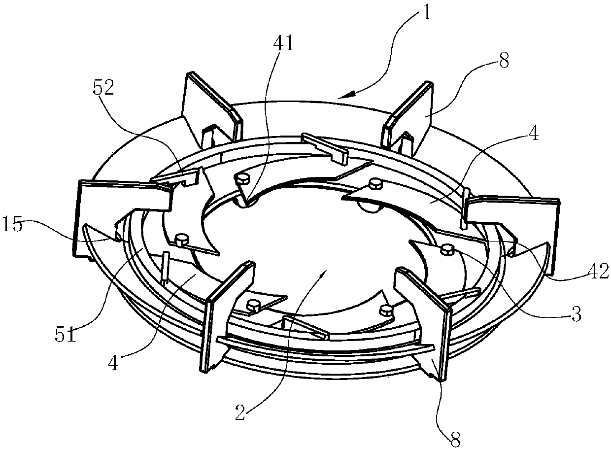
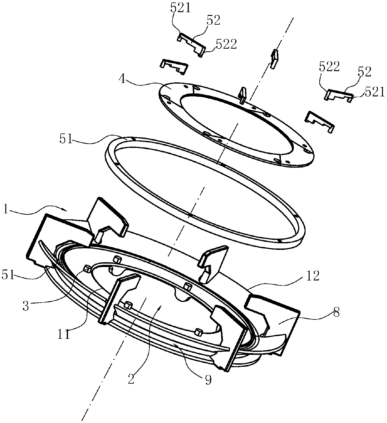
[0052] Such as Figure 1-6 As shown, the energy gathering hood for the stove in this embodiment includes an annular cover body 1, the height of the inner edge 11 of the cover body 1 is lower than the outer edge 12, and the main reason why the use of the cover body 1 can improve the thermal efficiency is that the energy gathering cover The cover body 1 effectively separates the flue gas and supplementary secondary air channels, and also regulates the flow direction of the secondary air. The inner edge 11 of the cover body 1 is surrounded by an opening 2 for the secondary air to enter the inner periphery of the cover body 1, and the cover body 1 is connected with an opening 2 that can at least partially enter the opening 2 along the radial direction, and the adjustment member enters the opening 2. In this state, the secondary air cannot enter the inner circumference of the cover body 1 due to being blocked by the regulating member, wherein the regulating member can enter the ope...
Embodiment 2
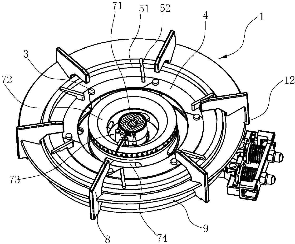
[0055] Such as Figure 7 As shown, the structure is basically the same as that of Embodiment 1, the only difference is that the adjustment member includes a pivot 3, a catch 4 arranged on the pivot 3, wherein the adjustment member is arranged on the upper surface of the bottom of the cover body 1, and Arranged along the circumferential direction of the cover body 1 , the cover body 1 is provided with guide grooves (not shown in the figure) on the corresponding upper surface of the bottom, and the pivot shaft 3 is slidably inserted into the guide grooves. The baffles 4 are manually rotated relative to the pivot 3, and each baffle 4 can be selectively adjusted according to the actual combustion conditions of the user. And the blocking plate 4 is rotated from outside to inside.
Embodiment 3
[0057] Such as Figure 8 As shown, the difference from Embodiment 2 is that the adjustment member includes a positioning block 10 arranged on the upper surface of the bottom of the cover body 1, and a positioning block 10 arranged along the circumference of the cover body 1, and a push plate 101 slidably connected to the positioning block 10. , wherein, the push plate 101 is provided with a positioning groove 1011 for the positioning block 10 to pass through, and the push plate 101 slides relatively through the positioning block 10, and each push plate 101 can be selectively adjusted according to the actual combustion conditions of the user , If there is overflowing liquid blocking the fire hole, the push plate 101 is slid from outside to inside in order to prevent the secondary air from being supplemented excessively.
PUM
 Abstract
Description
Claims
Application Information