AI technical title is built by Patsnap AI team. It summarizes the technical point description of the patent document.
A technology for fixing devices and aluminum templates, applied in positioning devices, feeding devices, clamping, etc., can solve problems such as poor splicing of aluminum templates, inaccurate cutting, and danger of aluminum templates
Active Publication Date: 2021-07-27
湖南中镆科技有限公司
View PDF7 Cites 0 Cited by
Summary
Abstract
Description
Claims
Application Information
AI Technical Summary
This helps you quickly interpret patents by identifying the three key elements:
Problems solved by technology
Method used
Benefits of technology
Problems solved by technology
[0005] In order to overcome the existing groove milling of aluminum formwork, the aluminum formwork is cut manually with a cutting machine. It is very dangerous to use a cutting machine to cut the aluminum formwork, and the cutting is not accurate, and the inaccurately cut aluminum formwork will cause good cutting. Aluminum templates cannot be spliced well, resulting in waste of aluminum templates. The technical problem of the present invention is to provide an aluminum template milling groove fixing device that can quickly and accurately cut aluminum templates
Method used
Image
Click on the blue label to locate the original text in one second.
Reading with bidirectional positioning of images and text.
Examples
Embodiment 1
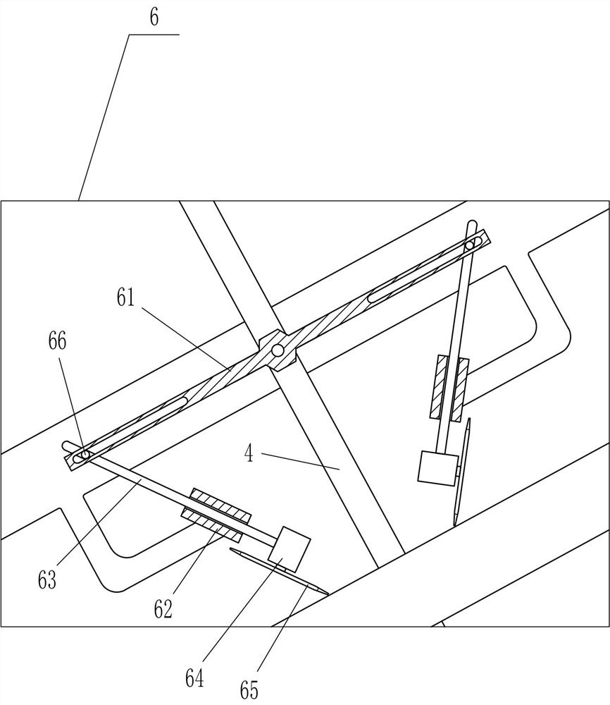
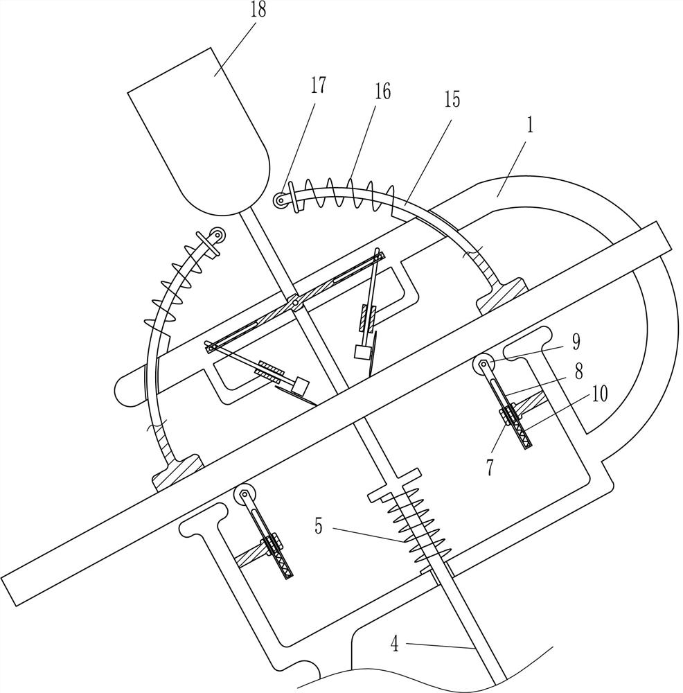
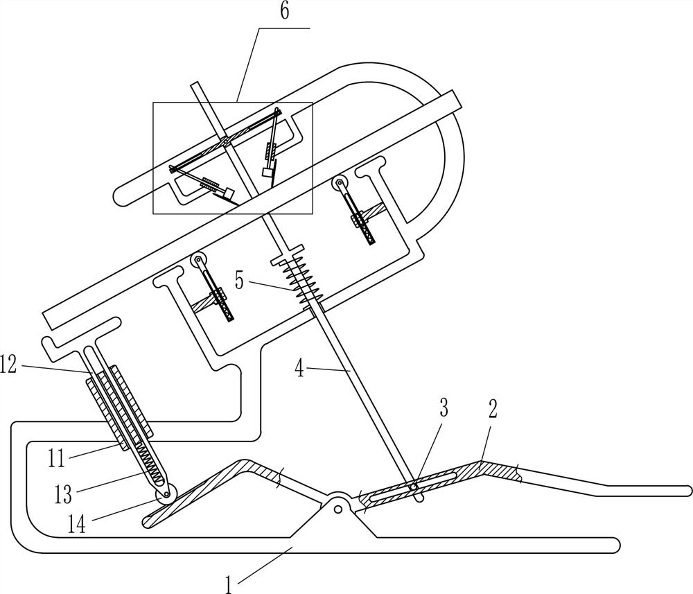
[0018] Aluminum template milling tank fixing device, such as Figure 1-3 As shown, including a bracket 1, the swing lever 2, the first pin lever 3, the first slider 4, the first spring 5, the cutting device 6, the second slider 7, the third slider 8, the first roller 9, The second spring 10, the stent 1 is rotated and connected to the swing rod 2, and the swing lever 2 is slidably connected to the first pin lever 3, the central sliding connection of the bracket 1 has a first slider 4, the bottom of the first slider 4. Attached to the first pin lever 3, the first slider 4 is connected to the stent 1 having a first spring 5, and the upper portion of the stent 1 is provided with a cutting device 6, and the bracket 1 is symmetrically provided with the second slider 7, the second slider 7 The third sliding rod 8 has a third slider 8, and the upper rotation of the third slider 8 has a first roller 9, and the third slider 8 is connected between the second sliding sleeve 7, and the second ...
Embodiment 2
[0023] On the basis of Example 1, if figure 1 As shown, there is also a third slider 11, the fourth slider 12, the third spring 13 and the second roller 14, and the left fixed connection of the bracket 1 has the third slider 11, the third slider 11 sliding The third spring 13 is connected between the third spring 13, and the bottom rotation of the fourth slider 12 is connected between the fourth slider 12 and the third slide 11, and the second roller 14 is connected. 14, the second roller 14 and the swing The rod 2 is in contact.
[0024] When used, the swing rod 2 is swing downward, and the second roller 14 is moved upward. The fourth slider 12 moves upward to the third spring 13, and the fourth slider 12 is moved upward. A function of supporting the aluminum template to prevent the aluminum template from sliding to the left to slide to the left, and after use, the fourth slider 12 is reset due to the elasticity of the third spring 13.
[0025] like image 3 As shown, there is als...
PUM
Abstract
The invention relates to a groove milling device, in particular to an aluminum formwork groove milling and fixing device. The technical problem of the present invention is how to provide an aluminum formwork groove milling and fixing device capable of cutting the aluminum formwork quickly and accurately. An aluminum formwork groove milling and fixing device includes a bracket, a swing rod and the like; the swing rod is rotatably connected to the bracket. In the present invention, the swing rod is pedaled to drive the cutting device to move downward through the first sliding rod to cut the aluminum template, and the downward movement of the first sliding rod can also drive the wedge-shaped plate to move downward, thereby the second The three rollers are extruded, so that the third roller drives the arc-shaped slide bar to slide down to contact the aluminum formwork to be cut, so that the fourth spring is compressed, so as to achieve the function of fixing the aluminum formwork when cutting it.
Description
Technical field [0001] The present invention relates to a milling slot device, and more particularly to an aluminum die milling groove fixing device. Background technique [0002] The aluminum template is a building aluminum alloy template for construction. It is a new generation template system that appears after the wood template and steel template. The aluminum template is designed by analog to extruded by special equipment, which can be freely combined according to different structural dimensions. The design and development and construction application of aluminum templates is a big development in the construction industry. The application of aluminum template system in the construction industry improves the construction efficiency of housing construction projects, including a lot of construction materials and artificial arrangements. When machining the aluminum template, the aluminum template is required to mill the aluminum template, and then the bend is made, making it int...
Claims
Application Information
Patent Timeline
Application Date:The date an application was filed.
Publication Date:The date a patent or application was officially published.
First Publication Date:The earliest publication date of a patent with the same application number.
Issue Date:Publication date of the patent grant document.
PCT Entry Date:The Entry date of PCT National Phase.
Estimated Expiry Date:The statutory expiry date of a patent right according to the Patent Law, and it is the longest term of protection that the patent right can achieve without the termination of the patent right due to other reasons(Term extension factor has been taken into account ).
Invalid Date:Actual expiry date is based on effective date or publication date of legal transaction data of invalid patent.

