Steel bar binding device

A technology of steel bar and driving device, which is applied in the direction of construction, building structure, and building material processing, etc., and can solve problems such as cumbersome, unsteady steel bar connections, and insufficient knob strength

Inactive Publication Date: 2021-02-02
钟赛梅
View PDF0 Cites 0 Cited by
  • Summary
  • Abstract
  • Description
  • Claims
  • Application Information

AI Technical Summary

Problems solved by technology

[0005] The technical problem to be solved by the present invention: Aiming at the problem that the binding of steel bars in the current building construction is cumbersome through manual manual operation, and the iron wires are manually turned for a long time. A steel bar binding device that quickly passes through the iron wire to make the knob, thereby effectively binding and fixing the steel bar

Method used


Image

  • Steel bar binding device
  • Steel bar binding device
  • Steel bar binding device

Examples


Embodiment Construction

[0018] The following will clearly and completely describe the technical solutions in the embodiments of the present invention. Obviously, the described embodiments are only some of the embodiments of the present invention, rather than all the embodiments. Based on the embodiments of the present invention, all other embodiments obtained by persons of ordinary skill in the art without making creative efforts belong to the protection scope of the present invention.

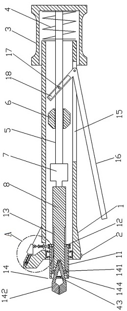
[0019] Such as figure 1 A steel bar binding device shown includes a hollow handle 1, a start switch 2, a sleeve 3, a first spring 4, a first slide bar 5, a first sliding sleeve 6, a motor 7, a rotating shaft 8, an annular slide rail 9, Annular slider 10, casing 11, transverse slider 12, transverse slide rail 13 and clamping device 14, start switch 2 is arranged on the left side of the bottom of hollow handle 1, sleeve 3 is arranged on the right part of hollow handle 1, sleeve The barrel 3 is slidingly connected with...


PUM


Abstract

The invention discloses a steel bar binding device, and belongs to the field of electrical equipment. According to the technical scheme, driving force is provided through a motor, under the action ofa sleeve, a clamping device can clamp an iron wire, a shifting block slides downwards to pull a third sliding rod, a third sliding sleeve, a fourth spring and a clamping block to slide downwards, dueto the fact that the fourth spring is connected between the clamping block and the third sliding sleeve, the third sliding rod slides downwards to drive the clamping block to be matched with a clamping groove, so that the clamping block fixes the third sliding rod, a stirring block drives a second sliding rod to move downwards through a second roller, the second sliding rod is in contact with a groove of a circular clamping plate, a third spring is compressed, therefore the function that the circular clamping plate fixes a sleeve is achieved, in this way, the iron wire can be clamped conveniently, and when resetting is needed, the stirring block is pushed to move upwards; and the motor rotates and can drive the clamping device to rotate through cooperation of a rotating shaft, an annular sliding rail, an annular sliding block and the sleeve, and therefore the function of effectively binding steel bars by screwing the iron wire is achieved.

Description

technical field [0001] The invention belongs to the field of building construction equipment, and in particular relates to a steel bar binding device. Background technique [0002] Before pouring the overall frame of the house, it is necessary to bundle the joints of the steel bars so that the steel bars are connected together as a whole to increase the bearing capacity of the overall frame of the house. The wire is tightened to connect the steel bar. If the iron wire cannot be fixed and tightened, the steel bar will be loosely connected. [0003] The current method of binding steel bars is to manually bind the steel bars, and manually use the clamp to turn the iron wires to achieve the connection of the steel bars. Because the manual operation is cumbersome, and the manual time is used to turn the iron wires, the knob is not strong enough. The steel bar connection is not solid, which affects the quality of the house frame. [0004] Therefore it is necessary to provide a s...

Claims


Application Information

Patent Timeline
Patent Type & Authority Applications(China)
IPC IPC(8): E04G21/12
CPCE04G21/123
Inventor 钟赛梅
Owner 钟赛梅
Why Eureka
Try Eureka