Pipeline working condition detection equipment, detection method and device and readable storage medium

A technology of detection equipment and detection method, which is applied in the fields of devices, readable storage media, detection methods, and pipeline condition detection equipment, and can solve problems such as inaccurate measurement of portable detection devices

Pending Publication Date: 2020-03-20
GREE ELECTRIC APPLIANCES INC
View PDF0 Cites 0 Cited by
  • Summary
  • Abstract
  • Description
  • Claims
  • Application Information

AI Technical Summary

Problems solved by technology

[0004] In view of this, the embodiment of the present invention provides a pipeline condition detection equipment, detection method, device and readable storage medium to solve the problem of inaccurate measurement of existing portable detection devices

Method used


Image

  • Pipeline working condition detection equipment, detection method and device and readable storage medium
  • Pipeline working condition detection equipment, detection method and device and readable storage medium
  • Pipeline working condition detection equipment, detection method and device and readable storage medium

Examples


Embodiment 1

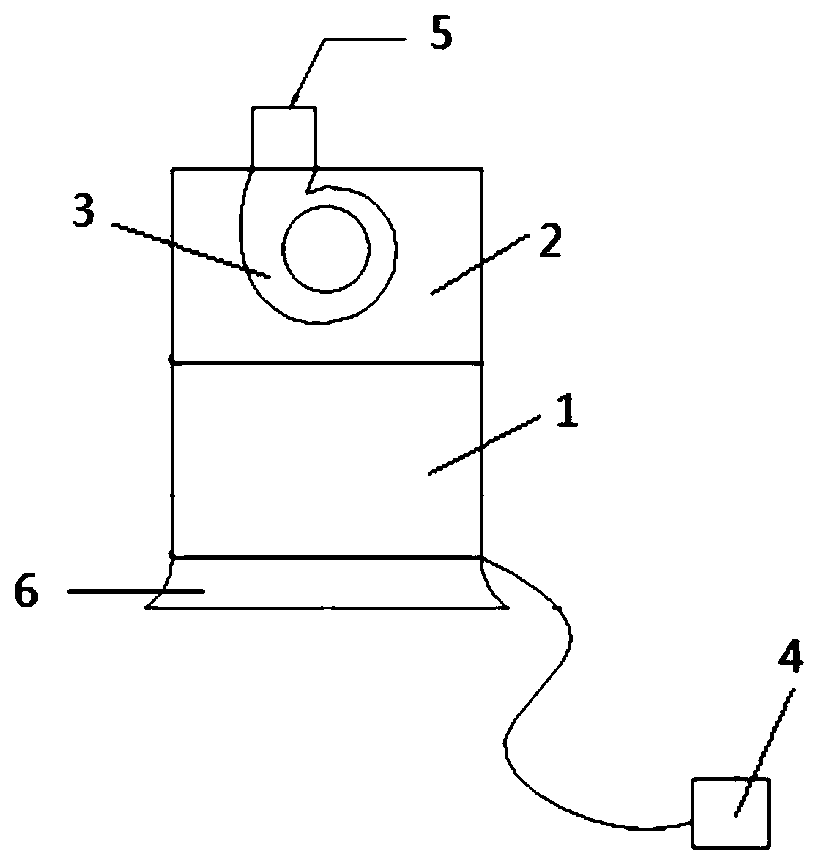
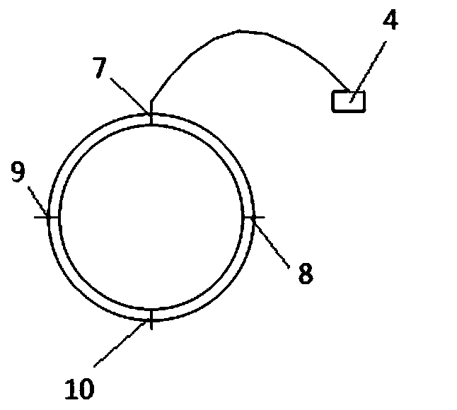
[0048] Embodiment 1 of the present invention provides a pipeline condition detection device, such as figure 1As shown, it includes a differential pressure flowmeter 1 and a processor 4. The differential pressure flowmeter 1 includes a diversion pipe section and a straight pipe section, the diversion pipe section is provided with a pressure sensor, and the straight pipe section is provided with a The first interface connected to the air inlet of the pipeline; the processor 4 is connected to the pressure sensor.

[0049] When the pipeline condition detection equipment is used to detect the pipeline to be tested, the gas enters the pipeline condition detection equipment through the diversion pipe section. In the embodiment of the invention, the straight pipe section may have different diameters according to the detected air volume. The first interface can be directly connected to the air inlet of the pipe to be tested, or can be connected through an adapter.

[0050] As a speci...

Embodiment 2

[0064] Embodiment 2 of the present invention provides a pipeline condition detection method, which is applied to pipeline condition detection equipment, the pipeline condition detection equipment includes a differential pressure flowmeter and a processor, and the differential pressure flowmeter includes a diversion pipe section and a A straight pipe section, the guide pipe section is provided with a pressure sensor, and the straight pipe section is provided with a first interface suitable for connecting with the air inlet of the pipeline to be tested. Such as Figure 4 Said, the pipeline working condition detection method of embodiment 2 of the present invention comprises the following steps:

[0065] S401: Obtain the pressure of the diversion pipe section of the differential pressure flowmeter.

[0066] The pressure of the draft pipe section is obtained through a pressure sensor in the draft pipe. As a specific implementation manner, after the fan is started, the pressure o...

Embodiment 3

[0097] Embodiment 3 of the present invention provides a pipeline condition detection device, which is applied to pipeline condition detection equipment. The pipeline condition detection equipment includes a differential pressure flowmeter and a processor. The differential pressure flowmeter includes a diversion pipe section and a A straight pipe section, the guide pipe section is provided with a pressure sensor, and the straight pipe section is provided with a first interface suitable for connecting with the air inlet of the pipeline to be tested. Such as Figure 5 As mentioned above, the pipeline condition detection device according to Embodiment 3 of the present invention includes an acquisition module 50 , a first processor 52 and a second processor 54 .

[0098] Specifically, the obtaining module 50 is configured to obtain the pressure of the guide pipe section of the differential pressure flowmeter.

[0099] The first processor 52 is configured to calculate the gas flow ...


PUM


Abstract

The invention discloses pipeline working condition detection equipment, a pipeline working condition detection method, a pipeline working condition detection device and a readable storage medium. Thepipeline working condition detection equipment comprises a differential pressure flowmeter and a processor, the differential pressure flowmeter comprises a flow guide pipe section and a straight pipesection, the flow guide pipe section is provided with a pressure sensor, the straight pipe section is provided with a first connector suitable for being connected with an air inlet of a to-be-detectedpipeline, and the processor is connected with the pressure sensor. When a to-be-detected working condition is accessed, gas enters the pipeline working condition detection equipment from the flow guide pipe section of the differential pressure flow meter and flows into the to-be-detected working condition through the straight pipe section and the first interface, connected with the air inlet of the to-be-detected pipeline, of the straight pipe section, and the working condition of the to-be-detected pipeline is obtained by acquiring pressure data of the flow guide pipe section and calculating. The pipeline working condition detection equipment can accurately obtain the working condition of the to-be-detected pipeline.

Description

technical field [0001] The invention relates to the technical field of household electrical appliances, in particular to a pipeline working condition detection device, a detection method, a device and a readable storage medium. Background technique [0002] In household appliances, the working condition of the fan, that is, the back pressure generated by the resistance coefficient of the pipe and some parts, is closely related to the working status of the fan. Insufficient estimation of the overall resistance coefficient of the product itself will cause the fan system to be mismatched and the product performance will not meet the standard; if the resistance coefficient of some parts of the product is not accurately calculated, it will be easy to find the optimization direction in the product development process and prolong the product development cycle ;Under consideration of the working conditions of the product users, the actual performance of the product will be far from ...

Claims


Application Information

Patent Timeline
Patent Type & Authority Applications(China)
IPC IPC(8): G01D21/02
CPCG01D21/02
Inventor 万博臣贾铌
Owner GREE ELECTRIC APPLIANCES INC
Why Eureka
Try Eureka