Audio data generation method, device and system and controller

An audio data and controller technology, which is applied in the parts of the TV system, pulse modulation TV signal transmission, TV and other directions, can solve the problems of increasing the number of calculations and low efficiency.

Active Publication Date: 2020-03-20
BEIJING QIYI CENTURY SCI & TECH CO LTD
9 Cites 3 Cited by

AI-Extracted Technical Summary

Problems solved by technology

[0005] The existing technology can only calculate two or two audio and video. When the number of videos is too large, the number of calculations required is also greatly increased, and the efficiency is...

Abstract

The embodiment of the invention provides an audio data generation method, device and system and a controller. The method comprises the following steps: generating a timestamp representing the currentrecording moment in a process of recording a video by a camera; writing the timestamp into the audio output chip to enable the audio output chip to generate time audio signals, and inputting the timeaudio signal to the camera, enabling the camera to generate time audio data representing the time audio signals, wherein the time audio data corresponds to the video recorded at the current recordingmoment; the audio signal is generated according to the timestamp, the timestamps are recorded in the audio data of the videos recorded by the camera according to the audio signals, and when the multiple videos need to be synchronized, the video synchronization points of the videos can be determined according to the timestamps recorded in the audio data, and due to the fact that each video only needs to be processed once, the synchronization efficiency of the multiple videos is improved.

Application Domain

Television system detailsPulse modulation television signal transmission +1

Technology Topic

EngineeringAudio signal +6

Image

  • Audio data generation method, device and system and controller
  • Audio data generation method, device and system and controller
  • Audio data generation method, device and system and controller

Examples

  • Experimental program(1)

Example Embodiment

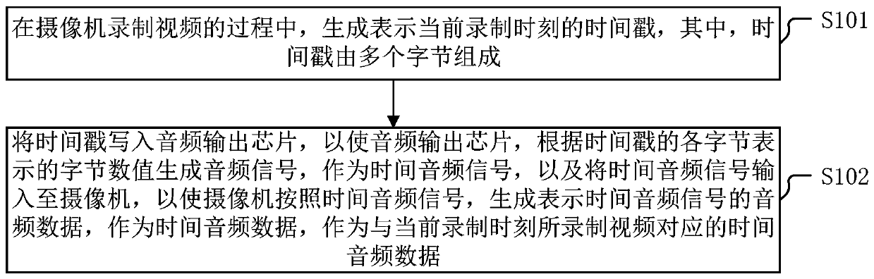
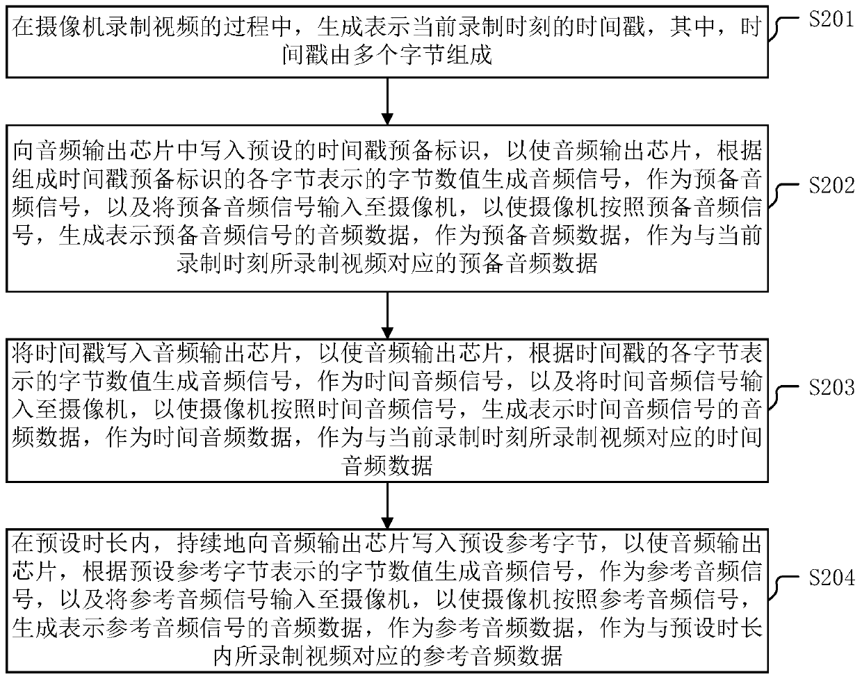
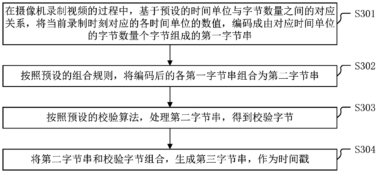
[0090] In order to provide an implementation scheme for improving the efficiency of synchronizing multiple videos, the embodiments of the present invention provide an audio data generation method, device, system, and controller. The embodiments of the present invention will be described below with reference to the accompanying drawings. And the embodiments in this application and the features in the embodiments may be combined with each other without conflict.
[0091] An embodiment of the present invention provides a method for generating audio data, and the method can be applied to a controller in a camera auxiliary device, wherein the camera auxiliary device further includes an audio output chip.
[0092] For ease of understanding, the audio output chip in the embodiment of the present invention is first briefly introduced:
[0093] In the embodiment of the present invention, the audio output chip is a chip that can output a PCM (Pulse Code Modulation, Pulse Code Modulation) audio signal according to an input control signal.
[0094]Among them, the audio output chip can input an audio signal according to the byte value represented by the written byte in each set clock cycle, wherein the audio signal generated by one byte value can be output in one clock cycle. voltage magnitude.
[0095] In one embodiment, the output precision of the audio output chip is set to 8-bit precision, and the frequency is set to 44.1kHZ, then the audio output chip can output 44,100 different analog quantities per second, and each output analog quantity corresponds to One voltage level, and the audio output chip with 8-bit precision can output 256 (2 to the 8th power) different voltage levels. The voltage difference of the lowest voltage -5V is 10V, which is equally divided into 256 parts, that is, the voltage difference between adjacent voltage levels is 0.0390625V.
[0096] As known to those skilled in the art, the value range of a byte value is 0 to 255, a total of 256. Therefore, the audio output chip can output a voltage corresponding to the byte value according to the byte value represented by the input byte. level of the audio signal.
[0097] Exemplarily, when the byte value represented by the input byte is 0, the output voltage level is -5V; when the byte value represented by the input byte is 125, the output voltage level is 0V. When the byte value represented by the byte is 255, the output voltage level is 5V.
[0098] In one embodiment, the corresponding relationship between the byte value represented by the input byte and the voltage level may be set according to the application scenario and experience. For example, the byte value of 0 may correspond to the voltage level of -5V, or the A byte value of 0 corresponds to a voltage level of 0V.
[0099] Below, the application scenarios of the present invention are briefly introduced:
[0100] A shooting scene in an embodiment of the present invention includes multiple cameras, and each camera shoots the stage scene from different angles. During the shooting process of each camera, the camera auxiliary device continuously inputs audio including time information to the camera. signal, so that the audio data of the video captured by the camera also contains time information. In this way, in the post-processing process, the recording time of the video can be determined through the audio data of the video, thereby improving the efficiency of synchronizing multiple videos.
[0101] The technical solutions in the embodiments of the present invention will be clearly and completely described below with reference to the accompanying drawings in the embodiments of the present invention.
[0102] In one embodiment of the present invention, a method for generating audio data is provided, which is applied to a controller in a camera auxiliary device, wherein the camera auxiliary device further includes an audio output chip, such as figure 1 As shown, the method includes the following steps:
[0103] S101: During the process of video recording by the camera, a timestamp representing the current recording moment is generated, wherein the timestamp is composed of multiple bytes.
[0104] In this step, those skilled in the art know that the timestamp is used to uniquely identify the time of a certain moment, for example, July 23, 2018.
[0105] In an embodiment of the present invention, in order to avoid the frequent generation of time stamps, the frequency of time stamp generation can be controlled by setting the time stamp generation period. During the process, a timestamp representing the current recording moment can be generated every 100ms.
[0106] In order to determine the current real-time recording time, the current time can be obtained by reading the RTC (Real time clock, real-time clock) time. As known to those skilled in the art, the time obtained by the RTC clock is usually yyyy-mm-dd, It is expressed in the form of hr:mi:se:ms, where yyyy is used to indicate the year, mm is used to indicate the month, dd is used to indicate the date, hr is used to indicate the date, mi is used to indicate the number of hours, and se is used to indicate the number of seconds. ms is used to represent the number of milliseconds.
[0107] Exemplarily, if the current time obtained by reading the RTC is 2019-11-29, 16-26-50-842, it means that the current time is November 29, 2019, 16:26:50, 842 milliseconds.
[0108] In one embodiment of the present invention, the time stamp may be composed of multiple bytes. For example, 9 bytes may be used to represent the current recording moment. In one embodiment, in order to ensure the accuracy of the time stamp, the Bytes plus a check byte.
[0109] Exemplarily, in the above example, the current moment is November 29, 2019, 16:26:50, 842 milliseconds, which means that the timestamp of the current moment can be 0x073E0B1D101A32034A. The specific timestamp generation method is detailed in the subsequent embodiments. introduce.
[0110] S102: Write the timestamp into the audio output chip, so that the audio output chip generates an audio signal according to the byte value represented by each byte of the timestamp as a time audio signal, and inputs the time audio signal to the camera, so that the camera According to the temporal audio signal, audio data representing the temporal audio signal is generated as temporal audio data as temporal audio data corresponding to the video recorded at the current recording time.
[0111] In this step, it can be known from the above description about the audio output chip that the audio output chip can input the byte value represented by the written byte to generate an audio signal in each clock cycle, wherein the clock cycle of the audio output chip It can be calculated according to the frequency of the audio output chip.
[0112] Exemplarily, when the frequency of the audio output chip is 44.1kHZ, the clock period of the audio output chip is about 0.002ms, that is, the audio output chip outputs an audio signal corresponding to a byte value represented by one byte every 0.002ms.
[0113] Exemplarily, when the timestamp is 0x073E0B1D101A32034A, it corresponds to 9 bytes, and the byte values ​​represented respectively are 7, 62, 11, 29, 16, 26, 50, 3, and 74. When the output of the audio output chip is When the voltage range is 0-10V, the time stamp is input to the audio output chip to output an audio signal with a voltage level of 0.0390625V×7=0.2734375V within the first 0.002ms, and output voltage within the second 0.002ms The audio signal with a level of 0.0390625V×62=2.421875V, calculated sequentially, it can be determined that the output voltage levels are 0.4296875V, 1.1328125V, 0.625V, 1.015625V, 1.953125V, 0.1171875V respectively within the 3rd to 9th 0.002ms and 2.890625V audio signal.
[0114] When the output voltage of the audio output chip ranges from -5V to 5V, subtract 5V from the voltage level corresponding to the byte value indicated by the above bytes. For example, the voltage level corresponding to the byte value size of 7 is 0.2734375V- 5V=-4.7265625V.
[0115] As known to those skilled in the art, in the prior art, when recording a video, a camera collects image information of the recording site through a lens, converts it into image/video data storage, collects the sound of the recording site through a microphone, and the microphone collects the image information of the recording site. The sound of the microphone is converted into analog audio information and input to the camera, and the camera converts the sound information collected by the microphone into audio data for storage. When generating a video, a video can have audio data of multiple audio tracks. The audio data of each audio track is independent of each other, and the source of its collection can be the same or different. Flexible configuration of the audio data that needs to be played according to its own needs.
[0116] In one embodiment of the present invention, the camera can not only collect and record the sound of the scene through the microphone, but also receive the time audio signal output by the audio output chip in the camera auxiliary device, and generate the audio representing the time audio signal according to the time audio signal. data.
[0117] In one embodiment, the camera can write the temporal audio data into a specified audio track of the currently recorded video according to a preset setting.
[0118] In the above-mentioned method for generating audio data of a controller applied to a camera auxiliary device provided by the embodiment of the present invention, in the process of video recording by the camera, a timestamp representing the current recording moment is generated, wherein the timestamp is composed of multiple bytes, And the time stamp is written into the audio output chip, so that the audio output chip generates an audio signal according to the byte value represented by each byte of the time stamp as a time audio signal, and the time audio signal is input to the camera, so that the camera follows the Time audio signal, generate audio data representing the time audio signal, as time audio data, as time audio data corresponding to the video recorded at the current recording moment, since the audio signal is generated according to the time stamp, the audio of the video recorded by the camera is made according to the audio signal. Time stamps are recorded in the data. When multiple videos need to be synchronized, the video synchronization point of each video can be determined according to the time stamps recorded in the audio data. The efficiency of synchronizing each video.
[0119] In an embodiment of the present invention, in the above-mentioned figure 1 Based on the audio data generation method shown, another audio data generation method is also provided, which is applied to a controller in a camera auxiliary device, wherein the camera auxiliary device further includes an audio output chip, such as figure 2 As shown, the method includes the following steps:
[0120] S201: During the process of video recording by the camera, a timestamp representing the current recording moment is generated, wherein the timestamp is composed of multiple bytes.
[0121] This step is the same as step S101 and will not be repeated here.
[0122] S202: Write a preset time stamp preliminary identification into the audio output chip, so that the audio output chip generates an audio signal according to the byte value represented by each byte constituting the time stamp preliminary identification, as the preliminary audio signal, and uses the preliminary identification The audio signal is input to the camera, so that the camera generates audio data representing the preliminary audio signal according to the preliminary audio signal, as preliminary audio data, as preliminary audio data corresponding to the video recorded at the current recording time.
[0123] In this step, in order to accurately identify the time stamp when determining the video recording time, a preset time stamp preparatory identifier may be written to the audio output chip before the time stamp is written to the audio output chip.
[0124] Among them, the above-mentioned time stamp preliminary identification can be any byte string agreed in advance. In order to further ensure that the time stamp preliminary identification will not affect the time stamp, the pre-agreed time stamp preliminary identification can be set as a byte with certain rules. .
[0125]Exemplarily, the time stamp preparation identifier can be 0x55FF55FF, which corresponds to 4 bytes, and the byte values ​​represented respectively are 85, 255, 85, and 255. When the output voltage of the audio output chip ranges from 0 to 10V, Then input the time stamp to the audio output chip to output an audio signal with a voltage level of 0.0390625V×85=3.3203125V in the first clock cycle, and output a voltage level of 0.0390625V×62=9.9609375V in the second clock cycle In the third clock cycle, the audio signal with the voltage level of 0.0390625V×85=3.3203125V is output, and the audio signal with the voltage level of 0.0390625V×62=9.9609375V is output in the fourth clock cycle.
[0126] In one embodiment, the camera may generate audio data representing the preparatory audio signal according to the preparatory audio signal, as preparatory audio data, as preparatory audio data corresponding to the video recorded within the preset duration.
[0127] S203: Write the timestamp into the audio output chip, so that the audio output chip generates an audio signal according to the byte value represented by each byte of the timestamp as a time audio signal, and inputs the time audio signal to the camera, so that the camera According to the temporal audio signal, audio data representing the temporal audio signal is generated as temporal audio data as temporal audio data corresponding to the video recorded at the current recording time.
[0128] This step is the same as step S102 and will not be repeated here.
[0129] S204: Continuously write preset reference bytes to the audio output chip within a preset time period, so that the audio output chip generates an audio signal according to the byte value represented by the preset reference byte as a reference audio signal, and uses The reference audio signal is input to the camera, so that the camera generates audio data representing the reference audio signal according to the reference audio signal, as the reference audio data, as the reference audio data corresponding to the video recorded within the preset duration.
[0130] In this step, in order to avoid the frequent generation of timestamps, after the timestamps are written into the audio output chip, preset reference bytes may be written to the audio output chip for a preset duration.
[0131] The preset duration may be determined according to actual requirements and experience, for example, may be 100ms, so as to ensure that the audio output chip can be written with a timestamp once every 100ms.
[0132] The above-mentioned preset reference byte may be a pre-agreed byte or multiple pre-agreed bytes. Similarly, in order to further pre-set reference bytes will not affect the time stamp, the pre-agreed reference byte can be The preset reference byte sets some special bytes.
[0133] Exemplarily, the preset reference byte may be 0x00, and the size of the byte value represented by it is 0. When the output voltage of the audio output chip ranges from 0 to 10V, the time stamp can be input to the audio output chip. Output the audio signal with a voltage level of -0V for 100ms. When the output voltage of the audio output chip ranges from -5V to 5V, input the timestamp into the audio output chip to output a voltage level of -5V for 100ms. audio signal.
[0134] In one embodiment, the camera may generate audio data representing the reference audio signal according to the reference audio signal, as the reference audio data, as the reference audio data corresponding to the video recorded within the preset duration.
[0135] In the above-mentioned another method for generating audio data of a controller applied to a camera auxiliary device provided by the embodiment of the present invention, in the process of video recording by the camera, a time stamp representing the current recording moment is generated, and written into the audio output chip. The preset time stamp preliminary identification, so that the audio output chip generates an audio signal according to the byte value represented by each byte constituting the time stamp preliminary identification, as a preliminary audio signal, and writes the time stamp into the audio output chip, so that the The audio output chip generates an audio signal according to the byte value represented by each byte of the timestamp as a time audio signal, and inputs the time audio signal to the camera, so that the camera generates audio data representing the time audio signal according to the time audio signal , as the time audio data, as the time audio data corresponding to the video recorded at the current recording moment, and within the preset duration, continuously write the preset reference bytes to the audio output chip, so that the audio output chip, according to the preset The byte value represented by the reference byte generates an audio signal as the reference audio signal, and the reference audio signal is input to the camera, so that the camera generates audio data representing the reference audio signal according to the reference audio signal, as the reference audio data, as the reference audio data. For the reference audio data corresponding to the video recorded within the preset duration, since the audio signal is generated according to the time stamp, the audio data of the video recorded by the camera according to the audio signal is recorded with a time stamp. The time stamp recorded in the audio data determines the video synchronization point of each video. Since each video only needs to be processed once, the efficiency of synchronizing multiple videos is improved.
[0136] In an embodiment of the present invention, a method for generating a timestamp is also provided, so as to realize the above steps S101 and S201, such as image 3 said, including:
[0137] S301: In the process of video recording by the camera, based on the corresponding relationship between the preset time unit and the number of bytes, encode the value of each time unit corresponding to the current recording moment into the number of bytes corresponding to the time unit. The first byte string consisting of sections.
[0138] In this step, the time unit is the unit representing time in each dimension, such as year, month, day, hour, minute, second, and millisecond.
[0139] The corresponding relationship between the preset time unit and the number of bytes may include:
[0140] The number of bytes corresponding to the time unit year is 2 bytes, that is, the year is represented by 2 bytes;
[0141] The number of bytes corresponding to the time unit month is 1 byte, that is, the month is represented by 1 byte;
[0142] The number of bytes corresponding to the time unit day is 1 byte, that is, the date is represented by 1 byte;
[0143] The number of bytes corresponding to the time unit is 1 byte, that is, the clock is represented by 1 byte;
[0144] The number of bytes corresponding to the time unit is 1 byte, that is, the minute is represented by 1 byte;
[0145] The number of bytes corresponding to the time unit second is 1 byte, that is, the second is represented by 1 byte;
[0146] The number of bytes corresponding to the time unit millisecond is 2 bytes, that is, the millisecond is represented by 2 bytes.
[0147] Exemplarily, when the current time is 10:52:6, 128 milliseconds on August 16, 2019, the value of the time unit year is 2019, and the corresponding number of bytes is 2 bytes, then 2019 is encoded as 0x073E, Correspondingly, the time units of month, day, hour, minute, second and millisecond are encoded as 0x08, 0x10, 0x0A, 0x34, 0x06, and 0x0080 respectively. When the current time is 16:26:50, 842 milliseconds on November 29, 2019, the first byte string obtained after encoding is: 0x073E, 0x0B, 0x1D, 0x10, 0x1A, 0x32, 0x034A.
[0148] S302: Combine each encoded first byte string into a second byte string according to a preset combination rule.
[0149] In this step, the first byte string may be combined in the order of the size of the time units. Exemplarily, in the above example, 0x07E308100A34060080 and 0x073E0B1D101A32034A may be obtained by combining.
[0150] S303: According to a preset check algorithm, process the second byte string to obtain check bytes.
[0151] In this step, in order to ensure the accuracy of the time stamp after transmission, a check byte can be added. In one embodiment, the above 9 can be added to the value represented by each bit in the byte, and added to 0xff Do an AND operation to get the checksum.
[0152] For example, when the second byte string is 0x073E0B1D101A32034A, after the above processing, the check byte can be obtained as 0xABB.
[0153] S304: Combine the second byte string and the check byte to generate a third byte string as a timestamp.
[0154] In this step, the second byte string and the check byte can be combined to generate a third byte string, which is used as a timestamp.
[0155] Exemplarily, combining 0x073E0B1D101A32034A and 0xABB, the obtained timestamp is 0x073E0B1D101A32034ABB.
[0156] In the above-mentioned time stamp generation method provided by the embodiment of the present invention, in the process of video recording by the camera, based on the corresponding relationship between the preset time unit and the number of bytes, the time unit of each time unit corresponding to the current recording moment may be a value, encoded into a first byte string consisting of the number of bytes corresponding to the time unit, and combining each encoded first byte string into a second byte string according to a preset combination rule, and According to the preset verification algorithm, the second byte string is processed to obtain the check byte, and the second byte string and the check byte are combined to generate the third byte string as a timestamp, so that accurate, Efficiently generate timestamps.
[0157] The embodiment of the present invention also provides a method for generating audio data, which is applied to a camera, such as Figure 4 shown, including:
[0158] S401: During the video recording process, receive a time audio signal input by the camera auxiliary device, where the time audio signal is generated by the camera auxiliary device according to the byte value represented by each byte of the timestamp representing the current recording moment.
[0159] In this step, in the process of video recording, the camera can receive the time audio signal input by the auxiliary device of the camera.
[0160] In one embodiment, before receiving the time audio signal input by the camera auxiliary device, a preparatory audio signal input by the camera auxiliary device may also be received, and after receiving the time audio signal input by the camera auxiliary device, the preset duration content, Continuously receive reference audio signals from camera auxiliary equipment.
[0161] S402: According to the time audio signal, generate audio data representing the time audio signal, as the time audio data, as the time audio data corresponding to the video recorded at the current recording time.
[0162] In this step, the generated time audio data is used as the audio data of the specific audio track of the recorded video.
[0163] In one embodiment, before generating the temporal audio data, audio data representing the preparatory audio signal may also be generated as preparatory audio data according to the preparatory audio signal input by the camera auxiliary device. And after generating the temporal audio data, according to receiving the reference audio signal input by the camera auxiliary device, audio data representing the reference audio signal is generated as the reference audio data.
[0164]In the above-mentioned method for generating a timestamp applied to a camera provided by the embodiment of the present invention, a time audio signal input by the camera auxiliary device may be received during the video recording process, and the time audio signal is the time stamp representing the current recording moment according to the camera auxiliary device. It is generated by the byte value represented by each byte of , and according to the time audio signal, the audio data representing the time audio signal is generated, as the time audio data, as the time audio data corresponding to the video recorded at the current recording moment, so that the generated The audio data carries a time stamp, so when multiple videos need to be synchronized, the video synchronization point of each video can be determined according to the time stamp recorded in the audio data. This improves the efficiency of synchronizing multiple videos.
[0165] Embodiments of the present invention also provide a method for determining a video recording moment, such as Figure 5 shown, including:
[0166] S501: Acquire a video with a to-be-determined recording time as the to-be-determined video, wherein the audio data of the to-be-determined video includes time audio data, and the time audio data is a time-representing audio signal generated by a camera recording the to-be-determined video according to the input time audio signal The audio data of the time audio signal is generated by the auxiliary equipment of the camera, and is generated according to the byte value represented by each byte of the timestamp representing the time stamp of the recording during the process of video recording by the camera.
[0167] In this step, the video to be determined is the video whose recording moment needs to be determined, which is recorded by a camera connected to the camera auxiliary device.
[0168] As known to those skilled in the art, the video recorded by the camera includes video data and audio data, and the video data and audio data of the video recorded at any time are corresponding, that is, the audio data can be determined after the recording time of the audio data is determined. The recording time of the video data corresponding to the data.
[0169] In one embodiment, before the temporal audio data, preliminary audio data may also be included, and after the temporal audio data, reference audio data may also be included.
[0170] In one embodiment, the audio data in a specific audio track of the video to be determined may be composed of preliminary audio data, temporal audio data and reference audio data, and each adjacent preliminary audio data, temporal audio data and reference audio data may be viewed as for one cycle.
[0171] S502: Based on the time audio data of the video to be determined, restore a time stamp representing the recording time of the time audio data.
[0172] In this step, the time audio data of the video to be determined may be obtained by reading the audio data of a preset audio track of the video to be determined, wherein the preset audio track is where the audio data generated by the input audio signal of the camera auxiliary device is located 's audio track.
[0173] In one embodiment, in order to accurately and quickly locate the time audio data, when the read audio data is pre-agreed preliminary audio data, the subsequently read audio data corresponding to the time stamp length is used as the time audio data data.
[0174] In one embodiment, as can be seen from the foregoing embodiments, the time audio data is generated according to the time audio signal, so the time audio data can be used to determine the byte string corresponding to the time audio information, and the time stamp can be restored from the time audio data.
[0175] S503: Determine the recording time indicated by the time stamp as the recording time of the temporal audio data.
[0176] In this step, the recording moment of the temporal audio data corresponding to the timestamp may be determined by the timestamp, thereby further determining the recording moment of the video data corresponding to the temporal audio data.
[0177] In one embodiment, in order to synchronize multiple videos, after each recording time of the multiple videos is determined, the video synchronization point of each video may be determined according to the recording time of each video, wherein the video synchronization point is when each video is in The synchronization point of the videos recorded at the same moment, which is used to match each video in time.
[0178] In the above-mentioned method for determining the video recording time provided by the embodiment of the present invention, the video of the to-be-determined recording time may be acquired as the to-be-determined video, wherein the audio data of the to-be-determined video includes time audio data, and the time audio data is the recording time of the to-be-determined video. The audio data representing the time audio signal generated by the camera according to the input time audio signal. The time audio signal is the camera auxiliary device. During the process of video recording by the camera, it is generated according to the byte value represented by each byte of the timestamp representing the recording time. and based on the time audio data of the video to be determined, restore the time stamp representing the recording time of the time audio data, and determine the recording time represented by the time stamp as the recording time of the time audio data, because the audio data of the video can be directly passed through. The recording moment of the video is determined, and then the video synchronization point of each video can be determined. Since each video only needs to be processed once, the efficiency of synchronizing multiple videos is improved.
[0179] After the recording time of the video is determined in step S503, the embodiment of the present invention further provides a video synchronization method, such as Image 6 shown, including:
[0180] S601: Among the videos to be determined whose recording moments have been determined, determine videos to be determined with the same recording moments as the target videos.
[0181] In this step, the video to be determined may include one recording moment, or may include multiple recording moments.
[0182] Exemplarily, the playback duration of the video to be determined is 10 minutes, and the determined recording time point is: the recording time of the second minute is 14:26 on July 26, 2019, and the recording time of the eighth minute is July 2019. At 14:32 on the 26th.
[0183] In one embodiment, among the to-be-determined videos of each determined recording time, the to-be-determined videos that have the same recording time can be used as the target video.
[0184] S602: In each target video, determine the time audio data with the same recording time as the video synchronization point.
[0185] In this step, the temporal audio data having the same recording moment may be determined as the video synchronization point.
[0186] Exemplarily, the playback duration of the first target video is from 10 minutes, the determined recording time of the second minute is 14:26 on July 26, 2019, and the playback duration of the second target video is determined from 20 minutes. The recording time of the 10th minute is 14:26 on July 26, 2019, and the 2nd minute of the first target video and the 10th minute of the second target video may be used as video synchronization points.
[0187] S603: Synchronize each target video according to the video synchronization point.
[0188] In this step, each target video may be synchronized according to the video synchronization point of each target video.
[0189] Exemplarily, the 2nd minute of the first target video and the 10th minute of the second target video are video synchronization points, then each video playback point corresponding to the first target video and the second target video at the same recording moment can be determined. .
[0190] In the above-mentioned video synchronization method provided by the embodiment of the present invention, among the videos to be determined whose recording moments have been determined, a to-be-determined video having the same recording moment may be determined as the target video, and in each target video, a video having the same recording moment will be determined. The time audio data at the moment is determined as the video synchronization point, and each target video is synchronized according to the video synchronization point. Since the video synchronization point of each video can be directly determined according to the recording time of each video, the synchronization of each video can be realized, so that each video can be synchronized. Video only needs to be processed once, increasing the efficiency of synchronizing multiple videos.
[0191] Based on the same inventive concept, according to the audio data generation method applied to the controller in the camera auxiliary device provided by the embodiment of the present invention, the embodiment of the present invention also provides an audio data generation device, which is applied to the controller in the camera auxiliary device. ,like Figure 7 As shown, the device includes:
[0192] A timestamp generating module 701, configured to generate a timestamp representing the current recording moment in the process of video recording by the camera, wherein the timestamp is composed of multiple bytes;
[0193] The timestamp output module 702 is configured to write the timestamp into the audio output chip, so that the audio output chip generates an audio signal according to the byte value represented by each byte of the timestamp as a time audio signal, and inputs the time audio signal to the camera, so that the camera generates audio data representing the time audio signal according to the time audio signal, as the time audio data, as the time audio data corresponding to the video recorded at the current recording time.
[0194] Further, the timestamp generation module 701 is specifically used to encode the numerical value of each time unit corresponding to the current recording moment into The first byte string is composed of the number of bytes corresponding to the time unit, and according to the preset combination rule, the encoded first byte strings are combined into the second byte string, and according to the preset combination rules The verification algorithm is to process the second byte string to obtain the check byte, and combine the second byte string and the check byte to generate the third byte string, which is used as a timestamp.
[0195] Further, the time stamp output module 702 is further configured to write a preset time stamp preparation identifier into the audio output chip before executing the time stamp writing to the audio output chip, so that the audio output chip is prepared according to the composition time stamp. The byte value represented by each byte of the identification generates an audio signal as a preliminary audio signal, and the preliminary audio signal is input to the camera, so that the camera generates audio data representing the preliminary audio signal according to the preliminary audio signal, as preliminary audio data, As the preparatory audio data corresponding to the video recorded at the current recording time.
[0196] Further, the timestamp output module 702 is further configured to continuously write preset reference bytes to the audio output chip within a preset time period after the timestamp is written into the audio output chip, so that the audio output chip, The audio signal is generated according to the byte value represented by the preset reference byte as the reference audio signal, and the reference audio signal is input to the camera, so that the camera generates the audio data representing the reference audio signal according to the reference audio signal as the reference audio data , as the reference audio data corresponding to the video recorded within the preset duration.
[0197] Based on the same inventive concept, according to the method for generating audio data applied to a camera provided by an embodiment of the present invention, an embodiment of the present invention further provides an apparatus for generating audio data, which is applied to a camera, such as Figure 8 As shown, the device includes:
[0198] The time audio signal receiving module 801 is used for receiving the time audio signal input by the camera auxiliary device in the process of recording the video, where the time audio signal is the byte value represented by the camera auxiliary device according to each byte representing the timestamp of the current recording moment Generated;
[0199] The audio data generation module 802 is configured to generate audio data representing the time audio signal according to the time audio signal, as the time audio data, as the time audio data corresponding to the video recorded at the current recording moment.
[0200] Based on the same inventive concept, according to the method for determining the video recording time provided by the embodiment of the present invention, the embodiment of the present invention also provides a device for determining the video recording time, such as Figure 9 As shown, the device includes:
[0201]The to-be-determined video acquisition module 901 is used to acquire the video of the to-be-determined recording time as the to-be-determined video, wherein the audio data of the to-be-determined video includes time audio data, and the time audio data is the time audio of the camera recording the to-be-determined video according to the input time. The audio data representing the time audio signal generated by the signal, the time audio signal is a camera auxiliary device, and is generated according to the byte value represented by each byte of the timestamp representing the time stamp of the recording time during the process of video recording by the camera;
[0202] Time stamp restoration module 902, for restoring the time stamp representing the recording moment of the time audio data based on the time audio data of the video to be determined;
[0203] The recording moment determining module 903 is configured to determine the recording moment represented by the time stamp as the recording moment of the temporal audio data.
[0204] Based on the same inventive concept, according to the video synchronization method provided by the embodiment of the present invention, the embodiment of the present invention also provides a video synchronization device, such as Figure 10 As shown, the device includes:
[0205] The target video determination module 1001 is used to determine the video to be determined with the same recording moment among the videos to be determined for each determined recording moment, as the target video;
[0206] The video synchronization point determination module 1002 is used to determine the time audio data with the same recording moment as the video synchronization point in each target video;
[0207] The target video synchronization module 1003 is used for synchronizing each target video according to the video synchronization point.
[0208] Based on the same inventive concept, an embodiment of the present invention also provides an audio data generation system, such as Figure 11 As shown, the system includes a camera 1101 and a camera auxiliary device 1102, and the camera auxiliary device 1102 includes a controller 11021 and an audio output chip 11022;
[0209] The controller 11021 is configured to generate a timestamp representing the current recording moment during the video recording process of the camera, wherein the timestamp is composed of multiple bytes, and write the timestamp into the audio output chip;
[0210] The audio output chip 11022 is used to generate an audio signal according to the byte value represented by each byte of the received timestamp, as a time audio signal, and input the time audio signal to the camera;
[0211] The camera 1101 is configured to generate audio data representing the time audio signal according to the received time audio signal, as the time audio data, as the time audio data corresponding to the video recorded at the current recording time.
[0212] Further, the controller 11021 is specifically used to encode the numerical value of each time unit corresponding to the current recording moment into the corresponding The first byte string composed of the number of bytes in the time unit, and according to the preset combination rule, the encoded first byte strings are combined into the second byte string, and according to the preset checksum The algorithm processes the second byte string to obtain a check byte, and combines the second byte string and the check byte to generate a third byte string, which is used as a timestamp.
[0213] Further, the controller 11021 is further configured to write a preset time stamp preparation identifier to the audio output chip before executing the time stamp writing to the audio output chip;
[0214] The audio output chip 11022 is also used to generate an audio signal according to the byte value represented by each byte constituting the time stamp preliminary identification, as a preliminary audio signal, and input the preliminary audio signal to the camera;
[0215] The camera 1101 is further configured to generate audio data representing the preliminary audio signal according to the preliminary audio signal, as preliminary audio data, as preliminary audio data corresponding to the video recorded at the current recording time.
[0216] Further, the controller 11021 is further configured to continuously write preset reference bytes to the audio output chip within a preset time period after writing the timestamp into the audio output chip;
[0217] The audio output chip 11022 is also used to generate an audio signal according to the byte value represented by the preset reference byte, as a reference audio signal, and input the reference audio signal to the camera;
[0218] The camera 1101 is further configured to generate audio data representing the reference audio signal according to the reference audio signal, as the reference audio data, as the reference audio data corresponding to the video recorded within the preset duration.
[0219] The embodiment of the present invention also provides a controller, such as Figure 12 As shown, it includes a processor 1201, a communication interface 1202, a memory 1203 and a communication bus 1204, wherein the processor 1201, the communication interface 1202, and the memory 1203 complete the communication with each other through the communication bus 1204,
[0220] The memory 1203 is used to store computer programs;
[0221] When the processor 1201 is used to execute the program stored in the memory 1203, the following steps are implemented:
[0222] In the process of video recording by the camera, a timestamp representing the current recording moment is generated, wherein the timestamp consists of multiple bytes;
[0223] Write the time stamp into the audio output chip, so that the audio output chip generates an audio signal according to the byte value represented by each byte of the time stamp as a time audio signal, and converts the time audio A signal is input to the camera, so that the camera generates audio data representing the time audio signal according to the time audio signal, as time audio data, as time audio data corresponding to the video recorded at the current recording moment .
[0224] The embodiment of the present invention also provides a camera, such as Figure 13 As shown, it includes a processor 1301, a communication interface 1302, a memory 1303 and a communication bus 1304, wherein the processor 1301, the communication interface 1302, and the memory 1303 complete the communication with each other through the communication bus 1304,
[0225] The memory 1303 is used to store computer programs;
[0226] When the processor 1301 is used to execute the program stored in the memory 1303, the following steps are implemented:
[0227] In the process of recording video, receiving a time audio signal input by the camera auxiliary device, the time audio signal is generated by the camera auxiliary device according to the byte value represented by each byte of the timestamp representing the current recording moment;
[0228] According to the time audio signal, audio data representing the time audio signal is generated as time audio data as time audio data corresponding to the video recorded at the current recording time.
[0229] The embodiment of the present invention also provides an electronic device, such as Figure 14 As shown, it includes a processor 1401, a communication interface 1402, a memory 1403 and a communication bus 1404, wherein the processor 1401, the communication interface 1402, and the memory 1403 communicate with each other through the communication bus 1404,
[0230] The memory 1403 is used to store computer programs;
[0231] When the processor 1401 is used to execute the program stored in the memory 1403, the following steps are implemented:
[0232] Obtain the video whose recording time is to be determined as the video to be determined, wherein the audio data of the video to be determined includes time audio data, and the time audio data is generated by the camera recording the video to be determined according to the input time audio signal. The audio data representing the time audio signal, which is a camera auxiliary device, is generated according to the byte value represented by each byte of the timestamp representing the time stamp of the recording time during the video recording process of the camera;
[0233] Based on the time audio data of the video to be determined, restore the time stamp representing the recording moment of the time audio data;
[0234] The recording time indicated by the time stamp is determined as the recording time of the time audio data.
[0235] The communication bus mentioned above for the controller, the camera and the electronic device may be a Peripheral Component Interconnect (PCI) bus or an Extended Industry Standard Architecture (EISA) bus or the like. The communication bus can be divided into an address bus, a data bus, a control bus, and the like. For ease of presentation, only one thick line is used in the figure, but it does not mean that there is only one bus or one type of bus.
[0236] The communication interface is used for communication between the above electronic device and other devices.
[0237] The memory may include random access memory (Random Access Memory, RAM), and may also include non-volatile memory (Non-Volatile Memory, NVM), such as at least one disk memory. Optionally, the memory may also be at least one storage device located away from the aforementioned processor.
[0238] The above-mentioned processor may be a general-purpose processor, including a central processing unit (Central Processing Unit, CPU), a network processor (Network Processor, NP), etc.; may also be a digital signal processor (Digital Signal Processing, DSP), an application-specific integrated circuit (Application Specific Integrated Circuit, ASIC), Field-Programmable Gate Array (Field-Programmable Gate Array, FPGA) or other programmable logic devices, discrete gate or transistor logic devices, discrete hardware components.
[0239] In another embodiment provided by the present invention, a computer-readable storage medium is also provided, where a computer program is stored in the computer-readable storage medium, and when the computer program is executed by a processor, any one of the above-mentioned applications to a camera is implemented Steps of an audio data generation method of a controller of an auxiliary device.
[0240] In another embodiment provided by the present invention, a computer-readable storage medium is also provided, where a computer program is stored in the computer-readable storage medium, and when the computer program is executed by a processor, any one of the above-mentioned applications to a camera is implemented The steps of the audio data generation method.
[0241] In another embodiment provided by the present invention, a computer-readable storage medium is also provided, and a computer program is stored in the computer-readable storage medium, and when the computer program is executed by a processor, any of the above video recording moments is realized steps of the method.
[0242] In yet another embodiment provided by the present invention, there is also provided a computer program product comprising instructions, which, when run on a computer, causes the computer to execute any audio of the above-mentioned embodiments applied to the controller of the camera auxiliary device Data generation method.
[0243]In yet another embodiment provided by the present invention, there is also provided a computer program product containing instructions, which, when run on a computer, cause the computer to execute any one of the above-described methods for generating video camera audio data.
[0244] In yet another embodiment provided by the present invention, there is also provided a computer program product including instructions, which, when running on a computer, enables the computer to execute any of the video recording moment methods in the above-mentioned embodiments.
[0245] In the above-mentioned embodiments, it may be implemented in whole or in part by software, hardware, firmware or any combination thereof. When implemented in software, it can be implemented in whole or in part in the form of a computer program product. The computer program product includes one or more computer instructions. When the computer program instructions are loaded and executed on a computer, all or part of the processes or functions described in the embodiments of the present invention are generated. The computer may be a general purpose computer, special purpose computer, computer network, or other programmable device. The computer instructions may be stored in or transmitted from one computer readable storage medium to another computer readable storage medium, for example, the computer instructions may be downloaded from a website site, computer, server or data center Transmission to another website site, computer, server, or data center is by wire (eg, coaxial cable, fiber optic, digital subscriber line (DSL)) or wireless (eg, infrared, wireless, microwave, etc.). The computer-readable storage medium may be any available medium that can be accessed by a computer or a data storage device such as a server, data center, etc. that includes an integration of one or more available media. The usable media may be magnetic media (eg, floppy disks, hard disks, magnetic tapes), optical media (eg, DVD), or semiconductor media (eg, Solid State Disk (SSD)), among others.
[0246] It should be noted that, in this document, relational terms such as first and second are only used to distinguish one entity or operation from another entity or operation, and do not necessarily require or imply any relationship between these entities or operations. any such actual relationship or sequence exists. Moreover, the terms "comprising", "comprising" or any other variation thereof are intended to encompass a non-exclusive inclusion such that a process, method, article or device that includes a list of elements includes not only those elements, but also includes not explicitly listed or other elements inherent to such a process, method, article or apparatus. Without further limitation, an element qualified by the phrase "comprising a..." does not preclude the presence of additional identical elements in a process, method, article or apparatus that includes the element.
[0247] Each embodiment in this specification is described in a related manner, and the same and similar parts between the various embodiments may be referred to each other, and each embodiment focuses on the differences from other embodiments. In particular, for devices, systems, controllers, cameras, electronic devices, computer-readable storage media, and computer program products, since they are basically similar to the method embodiments, the descriptions are relatively simple. For relevant details, refer to the method embodiments. Part of the description will do.
[0248] The above descriptions are only preferred embodiments of the present invention, and are not intended to limit the protection scope of the present invention. Any modification, equivalent replacement, improvement, etc. made within the spirit and principle of the present invention are included in the protection scope of the present invention.

PUM

no PUM

Description & Claims & Application Information

We can also present the details of the Description, Claims and Application information to help users get a comprehensive understanding of the technical details of the patent, such as background art, summary of invention, brief description of drawings, description of embodiments, and other original content. On the other hand, users can also determine the specific scope of protection of the technology through the list of claims; as well as understand the changes in the life cycle of the technology with the presentation of the patent timeline. Login to view more.
Why Eureka
Try Eureka