Eureka AIR delivers breakthrough ideas for toughest innovation challenges, trusted by R&D personnel around the world.

A decorative ring injection mold

A technology for injection molds and decorative rings, applied in the field of decorative ring injection molds, can solve the problem of small space for decorative rings 1, achieve the effect of compact core-pulling structure and improved safety performance

Active Publication Date: 2020-05-22
宁波远东制模有限公司
View PDF5 Cites 0 Cited by
  • Summary
  • Abstract
  • Description
  • Claims
  • Application Information

AI Technical Summary

Problems solved by technology

[0006] If the above-mentioned tunnel-type core-pulling structure is used to form the fastening hole 121 of the buckle, since the interior space of the above-mentioned decorative ring 1 is small and the number of buckles is large, it is impossible to set all twelve sets of tunnel-type core-pulling structures. Inside the bezel 1

Method used


Image

  • A decorative ring injection mold
  • A decorative ring injection mold
  • A decorative ring injection mold

Examples


Embodiment Construction

[0054] The present invention will be described in further detail below in conjunction with the accompanying drawings.

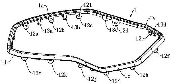
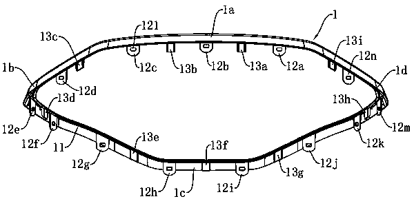
[0055] Since the decorative ring injection mold in this embodiment is used to form the decorative ring 1, the structure of the decorative ring injection mold in this embodiment corresponds to the decorative ring 1, so it is necessary to refer to the structure of the decorative ring 1 in the follow-up. figure 2 , image 3 and Figure 4 , no more details.

[0056] refer to Figure 5 , is an injection mold for a decorative ring disclosed in the present invention, including a movable mold 2 and a fixed mold 4 .

[0057] refer to Figure 5 and Figure 6, the movable mold 2 includes a movable mold bottom plate 21, a movable mold core 22, two support side plates 23 supported between the movable mold bottom plate 21 and the movable mold core 22, installed on the movable mold bottom plate 21 and positioned between the two support side plates 23 Between the ejec...


PUM


Abstract

The invention discloses an injection mold for a decorative ring, and solves the problem that the use effect of a decorative ring is influenced by abandoning a dense clamping structure due to the influence of factors such as an incompact traditional core pulling structure of an injection mold in the structural design of the decorative ring in the prior art. According to the invention, the decorative ring injection mold is characterized in that the decorative ring injection mold comprises a movable mold and a fixed mold; the movable mold comprises a movable mold bottom plate, a movable mold coreand an ejection mechanism; the movable mold core is provided with a forming convex ring, a first forming groove and a second forming groove on the parting surface of the movable mold; the movable mold core comprises a movable mold frame, a straight ejection block and a core pulling structure; the core pulling structure comprises a core pulling hole, a core pulling piece and a limiting sliding groove; the axis of the core pulling hole and the axis of the corresponding clamping hole to be formed are located on the same straight line; the other end of the core pulling piece is provided with a limiting clamping block matched with the limiting sliding groove in a clamped mode; and the limiting sliding groove inclines in the direction away from the clamping hole to be formed in the direction away from the movable mold core. The core pulling structure of the decorative ring injection mold is high in compactness.

Description

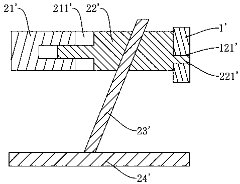
technical field [0001] The invention relates to an injection mold, in particular to an injection mold for a decorative ring. Background technique [0002] Injection mold is a tool used in injection molding, which can give plastic products a complete structure and a mold with precise dimensions. Injection molds generally include a movable mold and a fixed mold, and a cavity for forming the shape of a plastic product is formed between the movable mold and the fixed mold. [0003] When there are stuck holes on the plastic product, a tunnel-type core-pulling structure is usually set on the injection mold. refer to figure 1 , a tunnel-type core-pulling structure, used to form the card hole 121' on the plate-shaped workpiece 1', including a core 21', a core-pulling block 22', an inclined guide rod 23' and a push plate 24'; the core-pulling block 22' has and can only move left and right relative to the core 21', and the core-pulling block 22' has a post part 221' for forming the...

Claims


Application Information

Patent Timeline
Patent Type & Authority Patents(China)
IPC IPC(8): B29C45/33B29C45/44B29C45/26
CPCB29C45/2602B29C45/33B29C45/4435
Inventor 干洋洪黄金申吴照生
Owner 宁波远东制模有限公司
Why Eureka
Eureka Blog
Learn More