Forced interlock mechanism at the rear of the vacuum cabinet

An interlocking mechanism, behind-the-cabinet technology, applied in electrical components, electrical switches, circuits, etc., can solve problems such as operator misoperation, hidden dangers to personal safety, failure, etc., to avoid misoperation accidents, increase safety, components less effect

Active Publication Date: 2021-09-03
BEIJING SOJO ELECTRIC
View PDF0 Cites 0 Cited by
  • Summary
  • Abstract
  • Description
  • Claims
  • Application Information

AI Technical Summary

Problems solved by technology

[0004] In the traditional vacuum cabinet, the interlocking mechanism of the isolating switch, the circuit breaker switch and the grounding switch adopts a linkage transmission mode. During the operation process, there will often be jams or even failures, which will cause misoperation by the operator and cause personal injury. Safety poses a great hidden danger

Method used


Image

  • Forced interlock mechanism at the rear of the vacuum cabinet
  • Forced interlock mechanism at the rear of the vacuum cabinet
  • Forced interlock mechanism at the rear of the vacuum cabinet

Examples


Embodiment Construction

[0017] The following is a further detailed description of the rear mandatory interlocking mechanism of the vacuum cabinet of the present invention in conjunction with the accompanying drawings and specific embodiments:

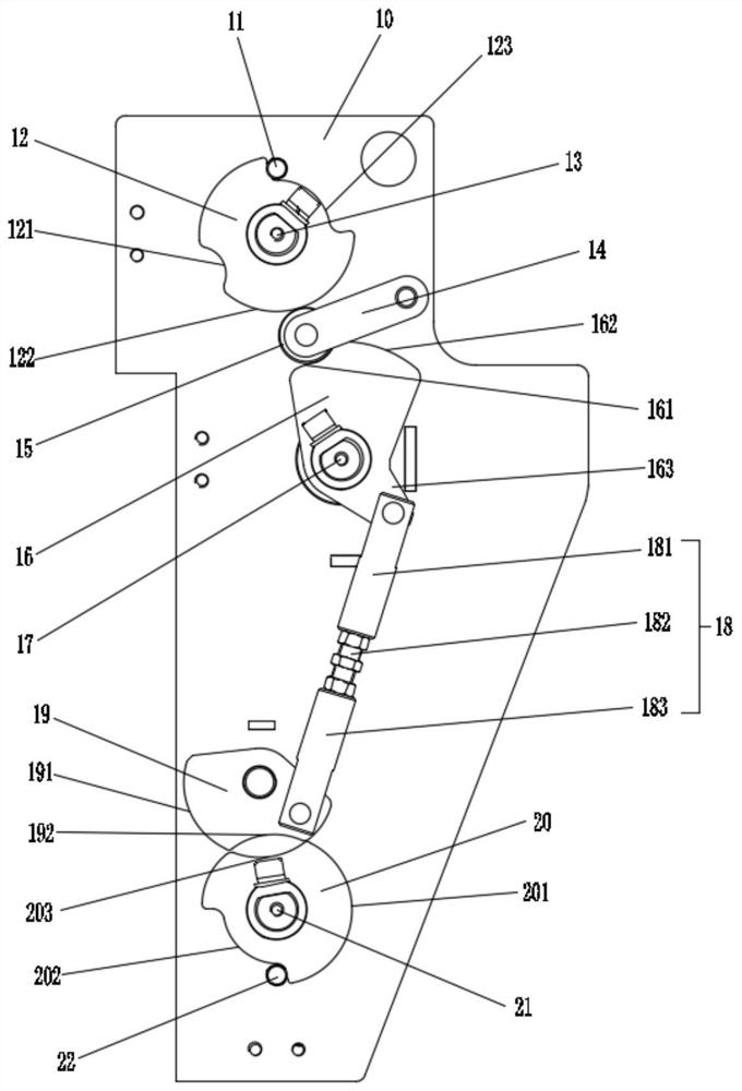
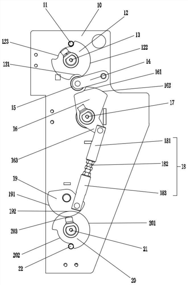
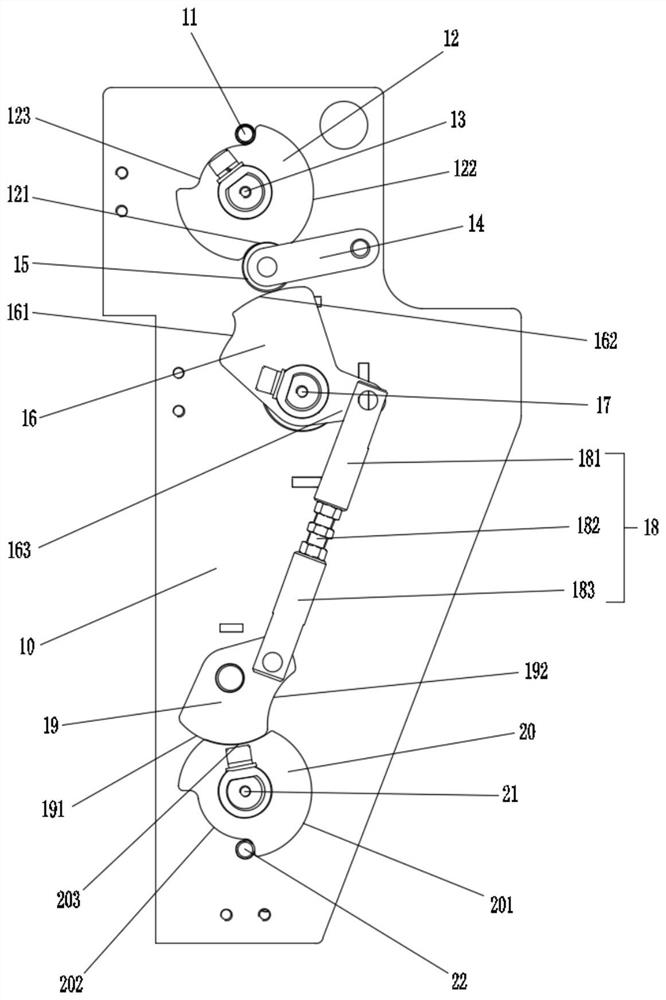
[0018] like figure 1 As shown, in this specific embodiment, the rear mandatory interlock mechanism of the vacuum cabinet of the present invention includes a rear plate 10, an isolation cam 12, an isolation main shaft 13, a circuit breaker cam 16, a circuit breaker main shaft 17, a grounding cam 20 and a grounding main shaft twenty one.

[0019] Back plate 10 is fixedly installed on the rear side wall of vacuum cabinet; Isolation cam 12 is fixedly installed on the isolation main shaft 13; shaft connection.

[0020] The circuit breaker cam 16 is fixedly installed on the circuit breaker main shaft 17; the circuit breaker main shaft 17 is located below the isolation main shaft 13, and passes through the back plate 10 to connect with the switch shaft (not shown i...


PUM


Abstract

A rear forced interlocking mechanism of a vacuum cabinet, comprising a rear plate, an isolation cam, an isolation main shaft, a circuit breaker cam, a circuit breaker main shaft, a grounding cam, and a grounding main shaft; the isolation cam is installed on the isolation main shaft, and the isolation main shaft is connected to the rotation shaft of an isolation switch ;The circuit breaker cam is installed on the main shaft of the circuit breaker, and the circuit breaker is connected with the rotating shaft of the circuit breaker switch; the grounding cam is installed on the main shaft of the grounding, and the grounding main shaft is connected with the rotating shaft of the grounding switch; There are first and second interlock linkage devices between the cams, so that when the isolating switch is opened, the circuit breaker cannot be closed; after the isolating switch is closed, the circuit breaker can be closed; after the circuit breaker is closed, the isolating switch and The grounding switch cannot be operated; and the circuit breaker cannot be closed after the grounding switch is closed. The invention has the advantages of simple structure and easy operation, high safety, and can reliably realize the interlocking function among the isolating switch, the circuit breaker and the grounding switch, and avoid misoperation accidents.

Description

technical field [0001] The invention relates to the technical field of power distribution vacuum cabinets, and more specifically relates to a rear-mounted compulsory interlocking mechanism of a vacuum cabinet. Background technique [0002] Vacuum cabinets are widely used in switching stations of power plants, substations of transmission lines, and user terminal substations for receiving electric energy. The vacuum cabinet is a power distribution equipment. In addition to the circuit breaker, there are isolation switches, grounding switches, transformers, lightning arresters and secondary circuits in the cabinet. [0003] Since the vacuum cabinet is a high-voltage power distribution device, its safety level is relatively high. The country requires that vacuum cabinets need to meet the five-proof requirements. The so-called five-proof requirements refer to: 1. Prevent the disconnection and closing of the isolating switch with load; When the switch is in the closed position, ...

Claims


Application Information

Patent Timeline
Patent Type & Authority Patents(China)
IPC IPC(8): H01H9/26
CPCH01H9/26H01H2009/265
Inventor 马宏祥奚鹏德李安顺石川李宗旺
Owner BEIJING SOJO ELECTRIC
Why Eureka
Try Eureka