Anesthesia depth monitoring device for anaesthesia department

A technology of anesthesia depth and monitoring device, applied in the field of anesthesia, can solve the problems of manual injection, loosening, less anesthesia dose, etc., and achieve the effects of increasing friction, preventing loosening, and reducing voids

Inactive Publication Date: 2020-03-27
刘坪坪
View PDF4 Cites 4 Cited by
  • Summary
  • Abstract
  • Description
  • Claims
  • Application Information

AI Technical Summary

Problems solved by technology

[0005] Aiming at the deficiencies in the prior art, the purpose of the present invention is to provide an anesthesia depth monitoring device for anesthesia department to solve the problem that the anesthesia dose used in small operations will vary due to the different sizes of syringes in the prior art. There are fewer syringes, so the syringes used will be smaller, and the upper end is usually fixed with a large syringe. When it is necessary to install a small syringe, the gap is too large, which is easy to cause loosening, and small operations usually require manual operation. injection problem

Method used


Image

  • Anesthesia depth monitoring device for anaesthesia department
  • Anesthesia depth monitoring device for anaesthesia department
  • Anesthesia depth monitoring device for anaesthesia department

Examples


specific Embodiment

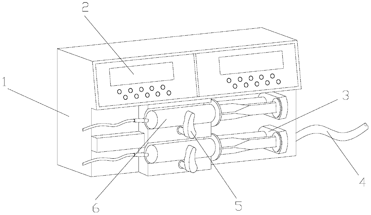
[0028] see Figure 1-Figure 8 , the specific embodiments of the present invention are as follows:

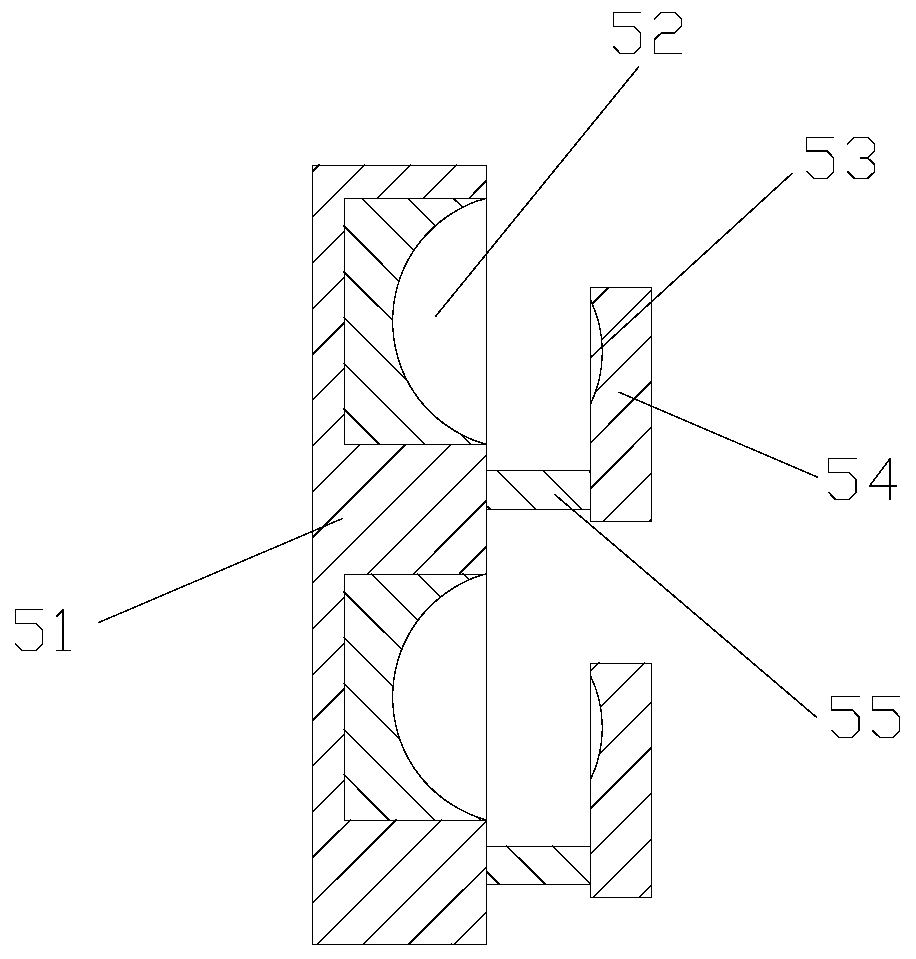
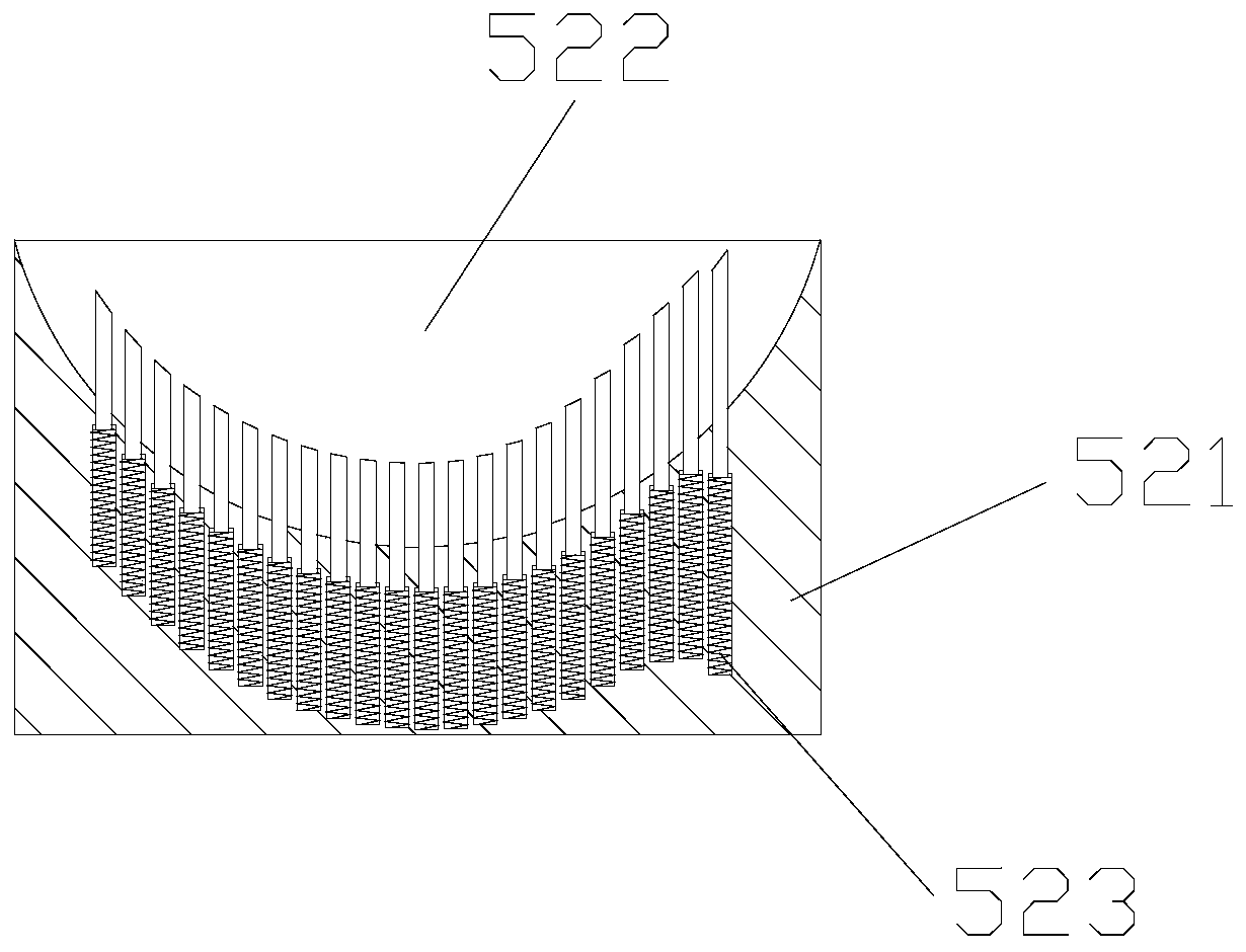
[0029] Its structure includes a monitoring machine 1, a display panel 2, a push frame 3, a monitoring tube 4, a clamping structure 5, and a needle tube 6. The display panel 2 is installed on the front of the monitoring machine 1 and is electrically connected, and the push frame 3 is installed on the The front of the monitoring machine 1 is embedded in the inside, the left end of the monitoring tube 4 is embedded and installed inside the monitoring machine 1, the clamping structure 5 is vertically installed on the front of the monitoring machine 1 and is mechanically connected, and the needle tube 6 is embedded in the clamping joint. The inner side of the structure 5 and adopts flexible connection; the clamping structure 5 includes a fixed plate 51, an inset fixed structure 52, an outer limit structure 53, a limit plate 54, and a movable structure 55, and the inset fixed structur...


PUM


Abstract

The invention discloses an anesthesia depth monitoring device for anaesthesia department. The device structurally comprises a monitoring machine, display panels, pushing frames, a monitoring tube, clamping structures and needle tubes; the display panels are arranged on the front side of the monitoring machine and are electrically connected; the pushing frames are arranged in the front side of themonitoring machine and is embedded inside the monitoring machine; the left end of the monitoring tube is embedded inside the monitoring machine; the clamping structures are vertically arranged on thefront side of the monitoring machine and are mechanically connected; the needle tubes are respectively embedded in the clamping structures and are movably connected; each clamping structure comprisesa fixing plate, an embedded fixing structure, the outer side limiting structure, a limiting plate and a movable structure, wherein the embedded fixing structure is embedded inside the fixing plate, and the outer side limiting structure is embedded inside the limiting plate and is movably connected. According to the invention, the clamping structures are respectively arranged outside the needle tubes, a space between the needle tubes and the monitoring machine is reduced by the pushing springs, and loosening is prevented, so that the needle tubes are better fixed, and automatic injection of needle tubes with different pipe diameters is realized.

Description

technical field [0001] The invention belongs to the field of anesthesia, and in particular relates to an anesthesia depth monitoring device for an anesthesiology department. Background technique [0002] At present, patients often need to be anesthetized when performing surgery. However, the dose control of anesthesia is particularly important. If it is too much, it may bring danger to the patient's life, and if it is too small, the anesthesia will fail during the patient's operation. The twitching caused by pain will affect the operation, so the anesthesia dose needs to be strictly calculated, thus deriving the anesthesia depth monitoring device for the department of anesthesiology, which can detect the depth of anesthesia more scientifically and automatically inject according to the actual situation anesthetic, but the prior art has the following deficiencies: [0003] Due to the different sizes of the syringes, and in small operations, the amount of anesthesia used will ...

Claims


Application Information

Patent Timeline
Patent Type & Authority Applications(China)
IPC IPC(8): A61M5/20A61M5/31
CPCA61M5/20A61M5/31
Inventor 刘坪坪
Owner 刘坪坪
Why Eureka
Try Eureka