
Display panel and display device

A display panel and display area technology, which is applied in instruments, computing, electrical digital data processing, etc., can solve the problem that the transmittance of the light emitting area cannot meet the requirements of the camera, high optical transmittance, etc.

Pending Publication Date: 2020-03-27
BOE TECH GRP CO LTD +1
View PDF6 Cites 15 Cited by
  • Summary
  • Abstract
  • Description
  • Claims
  • Application Information

AI Technical Summary

Problems solved by technology

However, the camera area requires high optical transmittance due to its imaging function, and the transmittance of the normal light-emitting area is far from meeting the needs of the camera

Method used


Image

  • Display panel and display device
  • Display panel and display device
  • Display panel and display device

Examples


Embodiment Construction

[0019] The application will be further described in detail below in conjunction with the accompanying drawings and embodiments. It should be understood that the specific embodiments described here are only used to explain the relevant disclosure, not to limit the disclosure. It should also be noted that, for the convenience of description, only the parts related to the disclosure are shown in the drawings.

[0020] It should be noted that, in the case of no conflict, the embodiments in the present application and the features in the embodiments can be combined with each other. The present application will be described in detail below with reference to the accompanying drawings and embodiments.

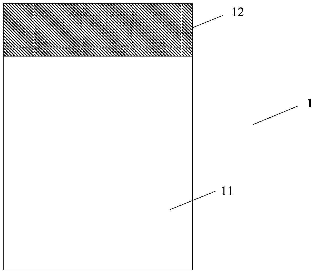
[0021] Please refer to figure 1 , figure 1 A schematic structural diagram of the display panel provided by the embodiment of the present application is shown.

[0022] The display panel 1 includes a first display area 11 and a second display area 12, each display area includes a pl...


PUM


Abstract

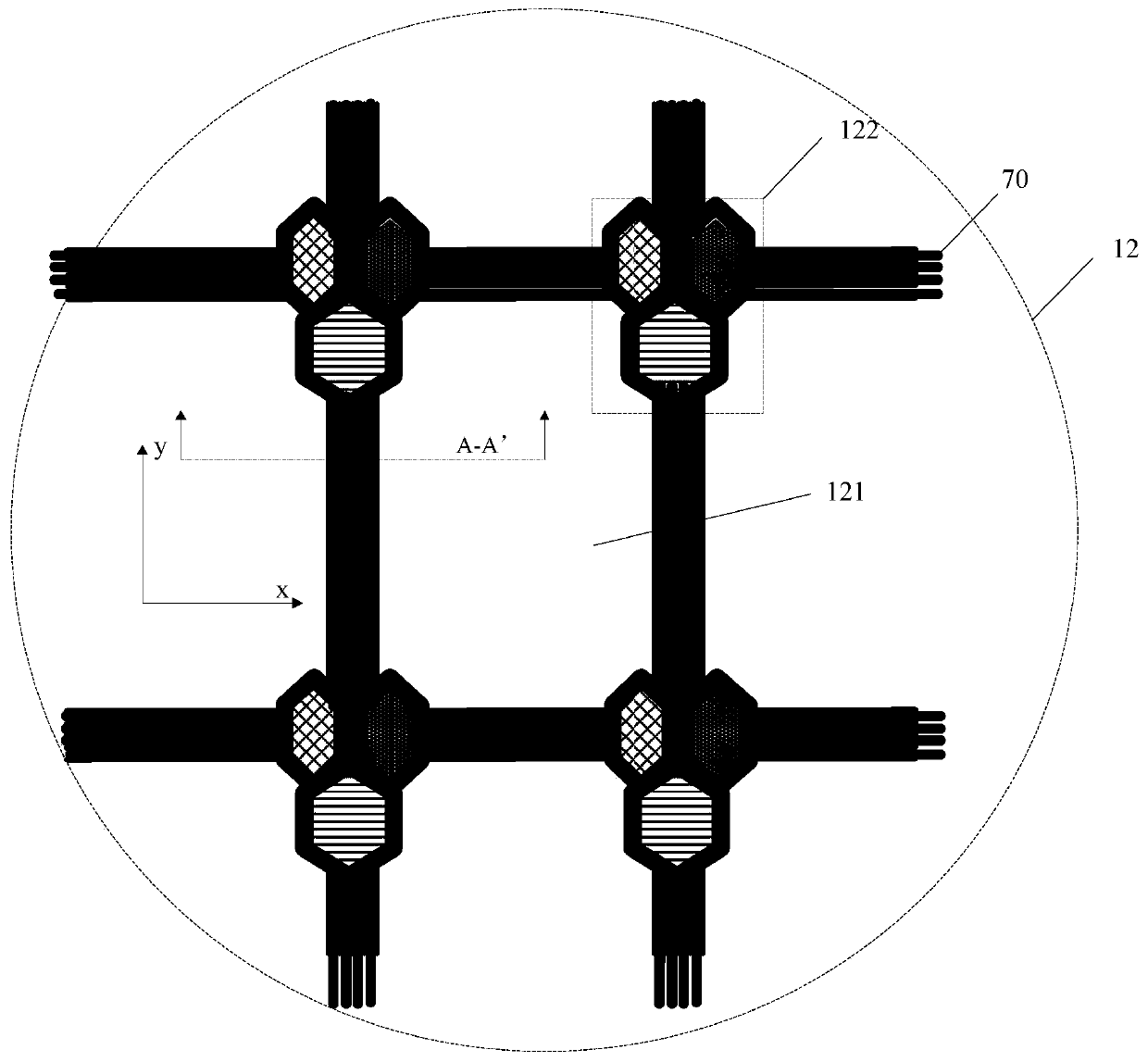
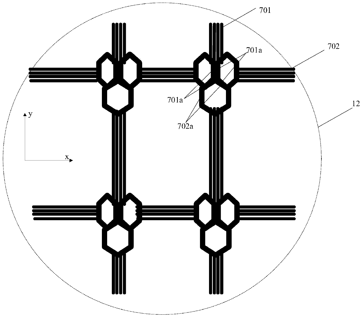
The invention discloses a display panel and a display device. The display panel includes comprises a first display area and a second display area, wherein the second display area comprises a pluralityof light-transmitting areas and a plurality of pixel unit areas; a first wiring area is arranged in the first direction; the first wiring area is connected with the adjacent pixel unit areas in the first direction; a second wiring area is arranged in the second direction; the second wiring area is connected with the adjacent pixel unit areas in the second direction, and the first direction and the second direction intersect; and a first gap exists between every two adjacent first wires in the first wiring area, and a second gap exists between every two adjacent second wires in the second wiring area. The display panel further comprises a substrate and a touch function layer, wherein the orthographic projection of the touch function layer on the substrate covers the orthographic projectionof the first gap and the orthographic projection of the second gap on the substrate. According to the embodiment of the invention, the gaps existing in the wiring area are shielded through the touchfunction layer, and the imaging quality is effectively improved.

Description

technical field [0001] The present application relates to the field of display technology, in particular to a display panel and a display device. Background technique [0002] With the development of technology, the market demand for display panels with high screen-to-body ratio is becoming more and more urgent, and display panels are developing in the direction of full-screen and thinner. The realization of full screen is inseparable from the under-screen camera technology, that is, when the imaging function is not needed, the camera emits light normally like other areas of the display panel; when the imaging function is required, the camera area has the normal imaging function. However, the camera area requires high optical transmittance due to its imaging function, and the transmittance of the normal light-emitting area is far from meeting the needs of the camera. The "H+L" design is adopted, that is, the normal area uses high PPI, and the area with high transmittance us...

Claims


Application Information

Patent Timeline
Patent Type & Authority Applications(China)
IPC IPC(8): G06F3/041
CPCG06F3/0412G09F9/30G09G3/30G06F3/0446G06F2203/04102G06F2203/04103G06F3/0445
Inventor 黄炜赟薛龙辉龙跃张微肖星亮
Owner BOE TECH GRP CO LTD
Learn More