Snap hinge device

A device and buckle technology, which is applied to wing parts, door/window accessories, buildings, etc., can solve problems such as impact, damage to the extension arm, and difficult operation

Active Publication Date: 2021-09-21
C M I CERNIERE MECCANICHE IND
View PDF10 Cites 0 Cited by
  • Summary
  • Abstract
  • Description
  • Claims
  • Application Information

AI Technical Summary

Problems solved by technology

[0010] The disadvantage of this known hinge is that, at the stage of connecting the door of the household appliance to the main body, the downward opening facing the oval hole and the supporting bushing can be hidden from the sight of the person appointed to make the connection, so that this connection This operation becomes difficult and / or slow, at least for workers without special experience
[0011] A further disadvantage of this known hinge is that, for example, in some cases a force is applied to the hinge pin of the door under force, for example by bending the extension arm with force, said force being directed towards the hinge pin into the respective the orientation of the bushing; the extension arm of said bushing is at risk of damage or breakage
[0012] Another disadvantage of the known hinge is that it may be affected by rotation irregularities and generate noise
[0013] Another disadvantage of said known hinge is that it allows an axial play in its carriage, which in some cases can be counterproductive if not prevented by other elements

Method used


Image

  • Snap hinge device
  • Snap hinge device
  • Snap hinge device

Examples


Embodiment Construction

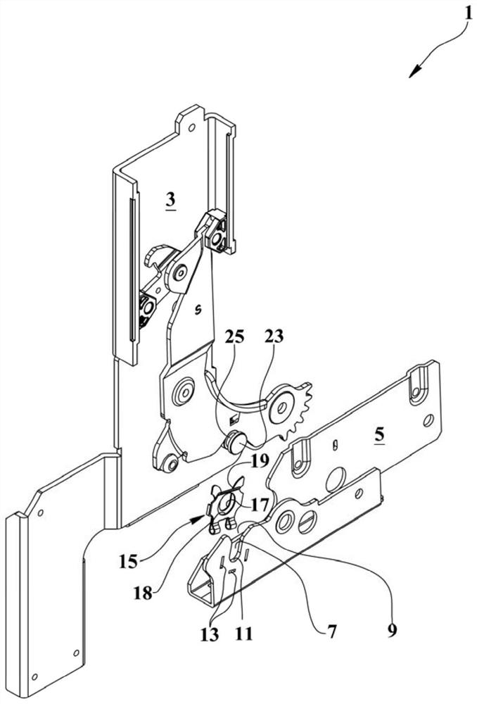
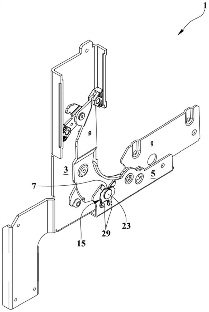
[0032] Please refer to Figure 1 to Figure 17 , reference numeral 1 denotes a snap-fit ​​hinge device comprising a first element 3 for being fixed to a body of an apparatus and a second element 5 for being fixed to a door of said apparatus, wherein said first element 3 and said second element 5 are connected to each other in the assembled state of the device so that the door can be rotated about the axis of rotation.

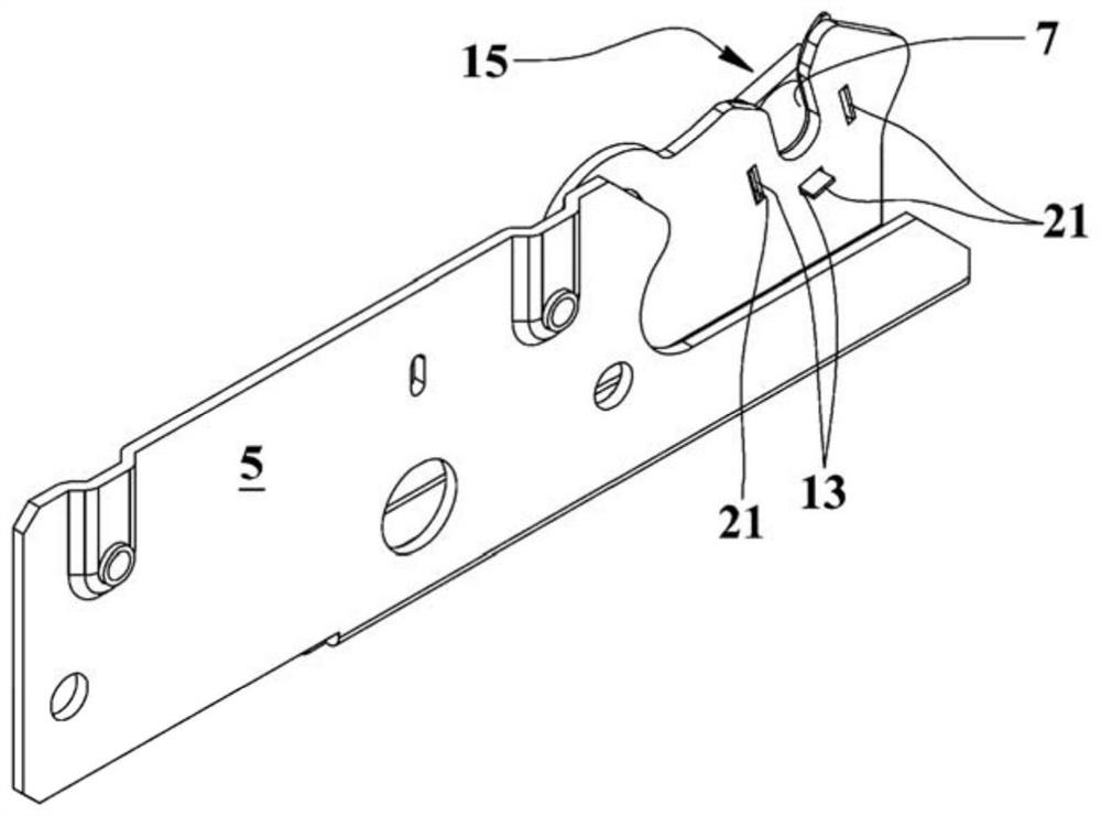
[0033] Said second element 5 is provided with an elongated groove 7 having an open end 9 and a closed end 11 .

[0034] The longitudinal axis of the elongated groove 7 can have almost any inclination with respect to the second element 5, and in the open state of the hinge means, the open end 9 can be as figure 2 Shown and preferably open upwards, or any other orientation.

[0035] Said second element 5 is also provided with a first connecting piece 13 made adjacent to the groove 7 and comprising, for example, a plurality of rectangular through-holes.

[0036...


PUM


Abstract

A snap hinge device comprising a first element (3) for fixing to a body of an appliance and a second element (5) for fixing to a door of said appliance, wherein in an assembled state of said appliance, The first element (3) and the second element (5) are interconnected to allow rotation of the door about an axis of rotation. Said second element (5) is equipped with a groove (7) of elongated shape, said groove (7) having an open end (9) and a closed end (11); said second element (5) is also equipped with There is a first connecting piece (13) close to said groove (7). Said device (1) also comprises hooking means (15) equipped with a first seat (17) having an opening (19), and facing almost said first seat (17) and a second seat (18) delimited by a continuous edge of itself, and said hooking means (15) comprising a second connecting piece (21) assigned to be associated with said The first link (13) engages to achieve a fixed state in which said opening (19) and said first seat (17) are aligned with the longitudinal axis of said groove (7), and towards said open end (9). Said first seat (17) and said groove (7) are designed to receive and accommodate the rod of a hinge pin (23) secured in a protruding manner to said first element ( 3) and define the axis of rotation. Said second seat (18) is designed to receive and house the head (26) of said hinge pin (23). The first element (3) and the second element (5) are separated from each other and fixed on the frame and the door respectively, can be connected to each other in a rotatable manner, and make the hinge pin (23) and its head (26) respectively engage with said first seat (17) and said second seat (18) to hinge said door to the frame of said equipment.

Description

technical field [0001] The present invention relates to hinges for household appliances, and to a snap-fit ​​hinge device particularly, but not exclusively, suitable for rotationally connecting a door having a lower and horizontal axis of rotation to an appliance such as a dishwasher. Background technique [0002] Known dishwashers have two modular hinges, each hinge having two members, one fixed to the underside of the main body or frame of the dishwasher and the other fixed to the corresponding lower base of the door. on the side. These components are separated and are engaged with each other by rotation after being respectively fixed to the main body and the door. This connection is made by an operator who manually moves the door to interconnect the interhook and swivel parts of the two parts of each hinge. [0003] A type of hinge is known for snap-fitting a revolving door about a horizontal axis lower than the body of a front-loadable domestic appliance, such as a dis...

Claims


Application Information

Patent Timeline
Patent Type & Authority Patents(China)
IPC IPC(8): E05D7/10
CPCE05Y2900/304E05D7/1077E05Y2600/528E05Y2600/53E05Y2600/63
Inventor 艾罗司·葛拉迪
Owner C M I CERNIERE MECCANICHE IND
Why Eureka
Try Eureka