Mixer and its shaft end sealing structure, composite sealing ring

A composite sealing ring and shaft end sealing technology, which is applied to the sealing of engines, cement mixing devices, mechanical equipment, etc., and can solve problems such as insufficient sealing performance

Active Publication Date: 2021-07-06
ZOOMLION HEAVY IND CO LTD
View PDF0 Cites 0 Cited by
  • Summary
  • Abstract
  • Description
  • Claims
  • Application Information

AI Technical Summary

Problems solved by technology

[0004] The purpose of the present invention is to provide a shaft end sealing structure of the mixer to solve the problem of insufficient sealing performance

Method used


Image

  • Mixer and its shaft end sealing structure, composite sealing ring
  • Mixer and its shaft end sealing structure, composite sealing ring
  • Mixer and its shaft end sealing structure, composite sealing ring

Examples


Embodiment Construction

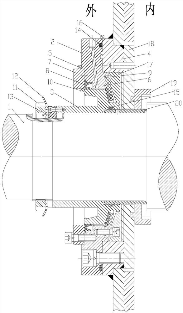
[0045] Specific embodiments of the present invention will be described in detail below in conjunction with the accompanying drawings. It should be understood that the specific embodiments described here are only used to illustrate and explain the present invention, and are not intended to limit the present invention.

[0046] In this solution, the axially inner side refers to the side relatively close to the stirring chamber of the mixer, and the axially outer side refers to the side relatively away from the stirring chamber of the mixer.

[0047] The present invention provides a shaft end sealing structure of a mixer, wherein the shaft end sealing structure of the mixer includes:
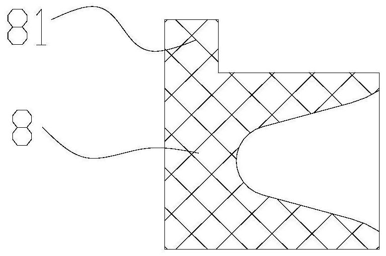
[0048] Spindle 1;

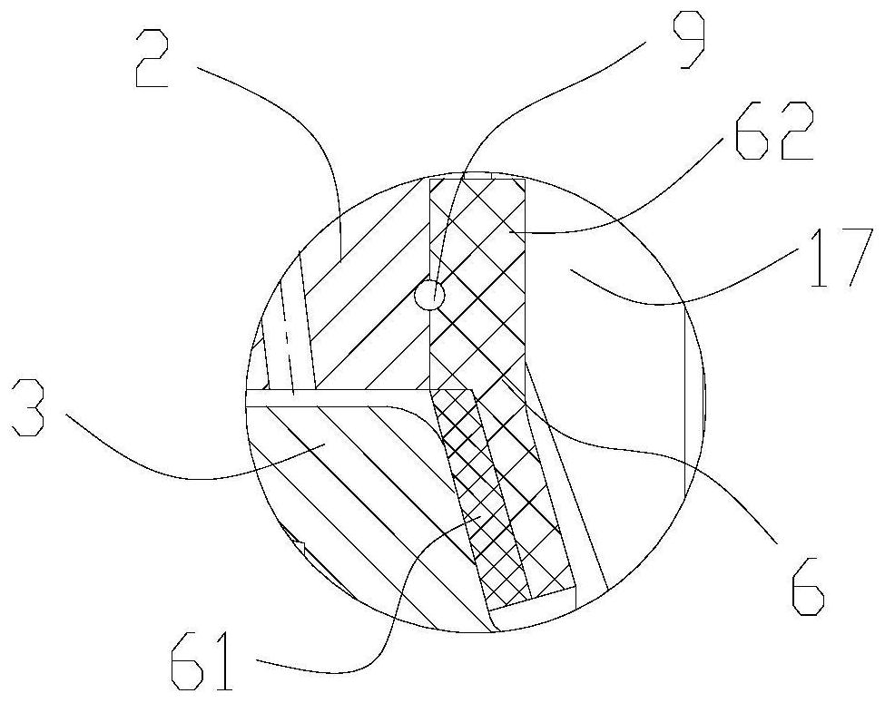
[0049] A rotating hub 3, the rotating hub 3 is fixedly sleeved on the rotating shaft 1, and the rotating hub 3 is provided with a tapered circular table surface facing inward in the axial direction;

[0050] A transition flange 2, the transition flange 2 is sheathed on the rot...


PUM


Abstract

The invention relates to the field of mixers, and discloses a mixer and its shaft end sealing structure and a composite sealing ring (6). The shaft end sealing structure of the mixer includes: a rotating shaft (1); a rotating hub (3); a transition flange (2), an annular gap is formed between the transition flange (2) and the rotating hub (3), and a lubricating oil passage is arranged in the transition flange (2); the composite sealing ring (6) It includes a rigid part (61) and an elastic part (62), the rigid part (61) is provided with an annular groove, and a first sealing ring (9) is arranged therein, and the elastic part (62) seals the annular gap and the Describe the rotating hub (3). Through the above technical solution, the composite sealing ring can provide an adjustable seal for the rotating hub, allowing lubricating oil to enter between the composite sealing rings of the rotating hub to provide lubrication, and can prevent the lubricating oil from passing through the gap between the transition flange and the composite sealing ring Spill leak.

Description

technical field [0001] The invention relates to the field of agitators, in particular to a shaft end sealing structure of an agitator, to an agitator, and to a composite sealing ring. Background technique [0002] A concrete mixer is a machine that mixes cement, sand and gravel aggregates and water and mixes them into concrete mixtures. The concrete mixer includes a stirring shaft and a mixing chamber. The stirring shaft is connected to the driving equipment outside the mixing chamber and extended into the mixing chamber to drive the stirring impeller to realize the stirring function. [0003] At the position where the stirring shaft passes through the mixing chamber, a sealing structure is required to avoid internal concrete leakage, and a supporting structure for the rotating shaft is also provided. Lubricating oil and corresponding sealing structures need to be provided between the supporting structure and the rotating shaft to ensure Avoid lubrication leaks. However, u...

Claims


Application Information

Patent Timeline
Patent Type & Authority Patents(China)
IPC IPC(8): F16J15/324F16J15/3252F16J15/3296F16J15/447B28C5/08
CPCB28C5/0818F16J15/324F16J15/3252F16J15/3296F16J15/447
Inventor 郭首君莫劲风聂一彪
Owner ZOOMLION HEAVY IND CO LTD
Why Eureka
Try Eureka