Rapid tripping device

A tripping device and fast technology, applied in electrical components, electrical switches, protection switch operation/release mechanisms, etc., can solve problems such as impact, impact on assembly efficiency, impact on the tripping function of circuit breakers, etc., to achieve high short-circuit breaking capacity, The effect of high breaking current

Pending Publication Date: 2020-04-03
JIANGSU DAQO KFINE ELECTRIC
View PDF1 Cites 4 Cited by
  • Summary
  • Abstract
  • Description
  • Claims
  • Application Information

AI Technical Summary

Problems solved by technology

[0013] However, this structural arrangement often hinders the pursuit of the volume ratio of the circuit breaker and affects the realization of integration and modularization; in addition, the heat generated by the circuit breaker during operation and the electromagnetic

Method used


Image

  • Rapid tripping device
  • Rapid tripping device
  • Rapid tripping device

Examples


Embodiment Construction

[0034] In order to make it easier for those skilled in the art to understand and implement the present invention, the present invention will be further described in detail below in conjunction with the accompanying drawings and specific embodiments.

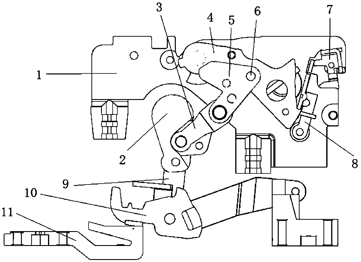
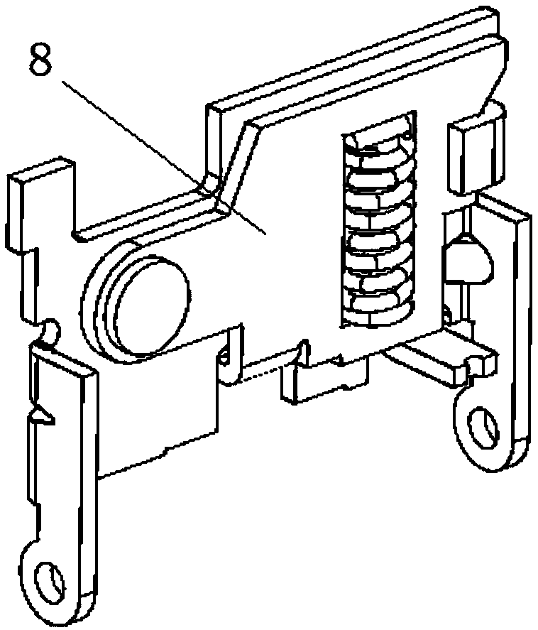
[0035] Such as figure 1 As shown, a quick release device of the present invention includes a mechanism bracket 1, an upper link 5, a lower link 3, a contact link 9, a main shaft 2, a moving contact 10, a static contact 11, and a jumper 4 , the first lock assembly 8, the second lock 7, two upper connecting rods 5 are located on both sides of the jumper 4, and the two upper connecting rods 5 pass through the upper connecting column 6 and the jumper 4 respectively. connected, the lower link is rotatably connected to the upper link at one end and is rotatably connected to the contact link at the other end, the lock is pivotally connected to the mechanism bracket 1, and In the overload state, the moving contact and the static contact...


PUM


Abstract

The invention discloses a rapid tripping device which comprises a mechanism support, a connecting rod device, a contact connecting rod, a main shaft, a moving contact, a static contact, a jump pin anda lock catch assembly device. One end of the jump pin is in lap joint with the lock catch assembly device, the other end of the jump pin is connected with the mechanism support through a rotating shaft, and the moving contact and the static contact make contact with each other in a non-overload state. In the over-loaded state, due to existence of electrodynamic repulsion, the acting force of thejump pin on the buckle surface on the lock catch assembly device is suddenly increased, so the lock plate overcomes the pressure of the lock catch pressure spring to deflect upwards; and the push surface pushes a second lock catch to rotate clockwise, the position of a first lock catch assembly is unlocked after the second lock catch rotates clockwise, the first lock catch assembly rotates clockwise, the buckle surface is separated from the jump pin, the jump pin rotates anticlockwise, the tripping process is completed, and the contact is opened.

Description

technical field [0001] The invention relates to the field of low-voltage electrical components and equipment, in particular to a mechanism of a current-limiting molded case circuit breaker. Background technique [0002] At present, molded case circuit breakers (MCCB, hereinafter referred to as circuit breakers) are commonly used in low-voltage power distribution systems to connect and break loads, protect the safety of lines and equipment, and belong to the category of low-voltage electrical appliances. [0003] The short-circuit breaking performance of a circuit breaker depends on various factors such as the opening time of the contacts, the speed of the contact movement, and the performance of the arc extinguishing chamber. In the case of other factors being the same, the earlier the circuit breaker contacts are opened, the better its short-circuit breaking performance will be. [0004] There are several kinds of short-circuit breaking processes of molded case circuit bre...

Claims


Application Information

Patent Timeline
IPC IPC(8): H01H71/10H01H3/54
CPCH01H3/54H01H71/10
Inventor 刘丰丰陈大江孙传金
Owner JIANGSU DAQO KFINE ELECTRIC
Why Eureka
Try Eureka