
Grass bundling rope bundling and knotting device

A knotting device and straw rope technology, which is applied to the parts of the binding machine, can solve the problems of time-consuming and low work efficiency

Active Publication Date: 2020-04-10
界首市宏利塑料股份有限公司
View PDF16 Cites 3 Cited by
  • Summary
  • Abstract
  • Description
  • Claims
  • Application Information

AI Technical Summary

Problems solved by technology

[0004] In order to overcome the above-mentioned technical problems, the object of the present invention is to provide a binding and knotting device for bale ropes: after clamping the ends of the bale ropes through the splints in the connecting spheres, the required binding of the binding objects The position is placed above the outlet slot of the console, and the first lifting cylinder extends upward at high speed through the top block to hit the connecting sphere and make a circular motion along the winding channel, and the bale rope driven by the connecting sphere is wound to the binding object. The connecting ball moves into the ball clamping groove in the knotting box to form two superimposed bale ropes, and the two propulsion cylinders extend to push the first combination box and the second combination box close, and start the heating wire of the hot-melt roller Heat the superimposed bale ropes into knots, start the second motor to convey the bundled ropes forward, the third lifting cylinder rises to push the clamping knife and the cutting knife up, and the first double-headed cylinder shrinks to drive the clamping knife holder Holding the bale rope, the cutting knife cuts the bale rope, the second double-headed cylinder extends to loosen the end of the bale rope, and the bale rope binds the binding objects, which solves the need of the existing semi-automatic tying machine for each tying knot. Manually insert the rope into the binding machine for the next binding and knotting. This process consumes a lot of time and the work efficiency is low.

Method used


Image

  • Grass bundling rope bundling and knotting device
  • Grass bundling rope bundling and knotting device
  • Grass bundling rope bundling and knotting device

Examples


Embodiment 1

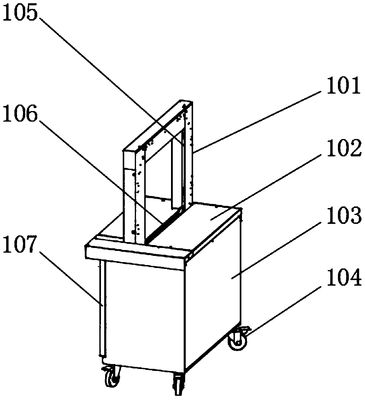
[0035] see Figure 1-10 As shown, the present embodiment is a binding and knotting device for bale ropes, including a mounting frame 101, a binding box 103, an operating console 102 is installed on the top of the binding box 103, and an outlet slot 106 is provided at the central axis of the operating console 102. The binding box 103 is equipped with a mounting frame 101 above the outlet slot 106, and the inside of the mounting frame 101 is provided with a drop slot 105;

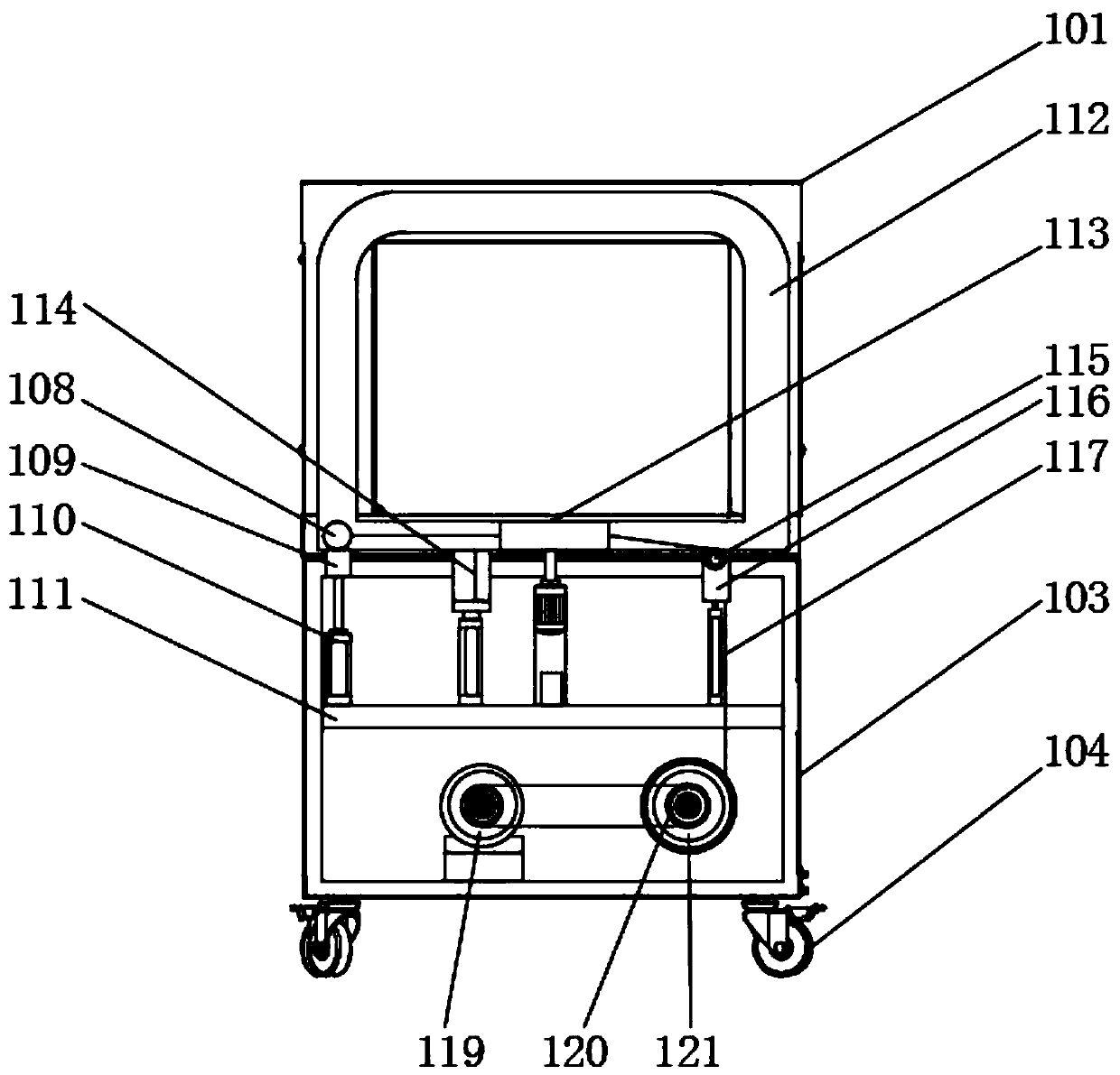
[0036] The inside of the installation frame 101 and the top of the inner cavity of the operating table 102 are equipped with a winding channel 112, and the inside of the winding channel 112 is movably equipped with a connecting sphere 108, and a knotting box 113 is installed in the middle of the bottom of the winding channel 112, and a knotting box 113 is installed. A clamping and cutting mechanism 114 is provided at the end away from the connecting sphere 108;

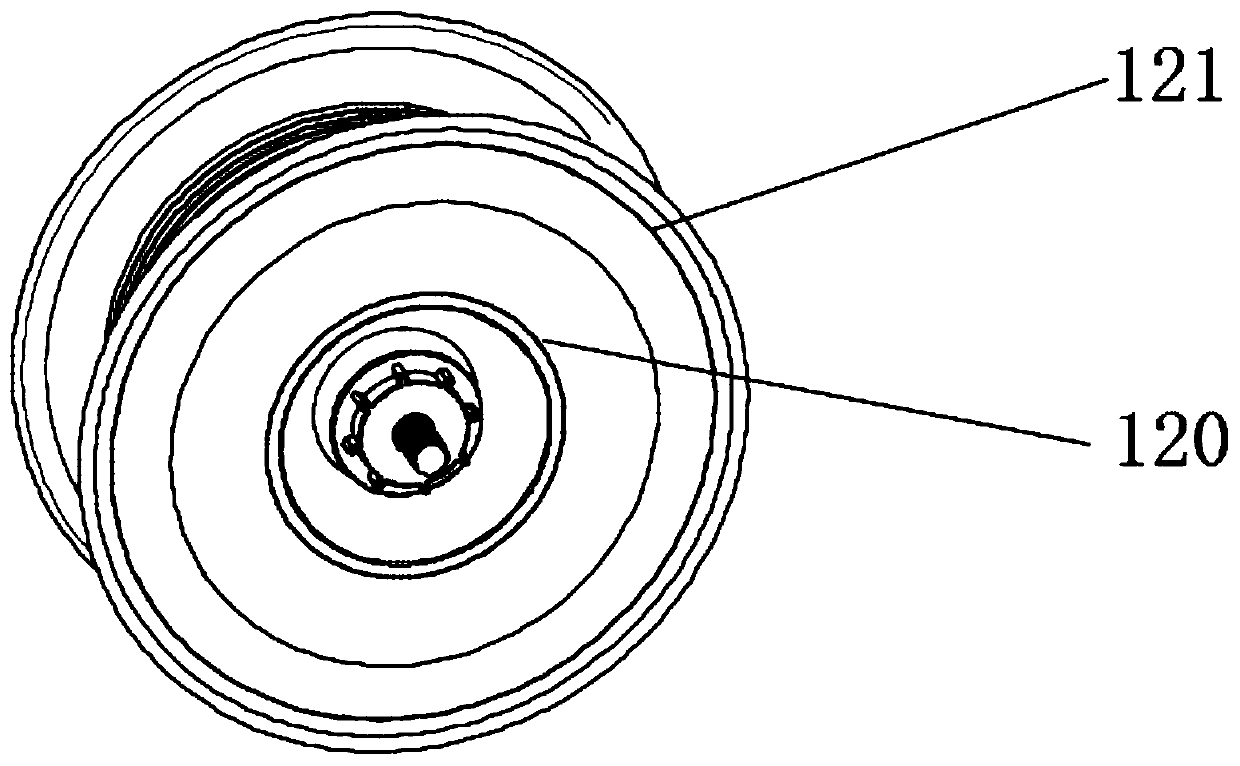
[0037] A first motor 119 is installed at the bo...


PUM


Abstract

The invention discloses a grass bundling rope bundling and knotting device. The grass bundling rope bundling and knotting device comprises a mounting rack and a bundling box; an operating table is mounted at the top of the bundling box; a wire outlet groove is formed in the axle wire of the operating table; the mounting rack is mounted above the wire outlet groove in the bundling box; a wire falling groove is formed in the inner side of the mounting rack; wire winding channels are separately mounted in the mounting rack and the top of the inner cavity of the operating table; wire connecting spheres are movably mounted in the wire winding channels; clamping plates in the wire connecting spheres are close, after the ends of grass bundling rope are clamped, when the wire connecting spheres docircular motion, the grass bundling ropes driven by the wire connecting spheres are wound on bundling objects, hot melting rollers are heated to perform hot melting and knotting on the stacked grassbundling ropes, first double-head cylinder shrink to drive a clamping tool to clamp the grass bundling ropes, a cut-off tool cuts off the grass bundling ropes, and the grass bundling ropes bundle thebundling objects; the grass bundling rope bundling and knotting device completes the bundling and knotting process of the bundling objects automatically, so that the working efficiency is greatly improved; and the grass bundling rope binding and knotting device is simple in structure, and is low in cost.

Description

technical field [0001] The invention relates to the technical field of packing and bundling, in particular to a bundling and knotting device for hay ropes. Background technique [0002] Rope knotters are used primarily in large rectangular balers for the movement of straw, hay, silage and similar substances and in recycling applications such as for baling paper, fabric, sheet metal and the like, currently, Knotters and their components cannot be produced independently in China, and are almost completely dependent on imports. [0003] Therefore, in order to achieve the purpose of bundling and knotting with a simple device, the patent application number CN201721299172.9 discloses a semi-automatic strapping machine, including a carrier and a packer connected to the carrier, and the top of the carrier is a weighing platform , there is a gravity introduction device inside, a weighing sensor is provided at the bottom of the gravity introduction device, an acousto-optic warning li...

Claims


Application Information

Patent Timeline
Patent Type & Authority Applications(China)
IPC IPC(8): B65B13/26B65B13/32
CPCB65B13/26B65B13/32
Inventor 刘立平王翊伟李影
Owner 界首市宏利塑料股份有限公司
Features
  • Generate Ideas
  • Intellectual Property
  • Life Sciences
  • Materials
  • Tech Scout
  • Unparalleled Data Quality
  • Higher Quality Content
  • 60% Fewer Hallucinations
Learn More