
Method for assembling ball bearing combined piece

A technology of ball bearings and assemblies, applied in the direction of ball bearings, bearing elements, shafts and bearings

Inactive Publication Date: 2003-05-28
TORRINGTON COMPANY
View PDF1 Cites 1 Cited by
  • Summary
  • Abstract
  • Description
  • Claims
  • Application Information

AI Technical Summary

Problems solved by technology

However, this polymer ball bearing cage can only be limited to low temperature and low strength applications

Method used


Image

  • Method for assembling ball bearing combined piece
  • Method for assembling ball bearing combined piece
  • Method for assembling ball bearing combined piece

Examples


Embodiment Construction

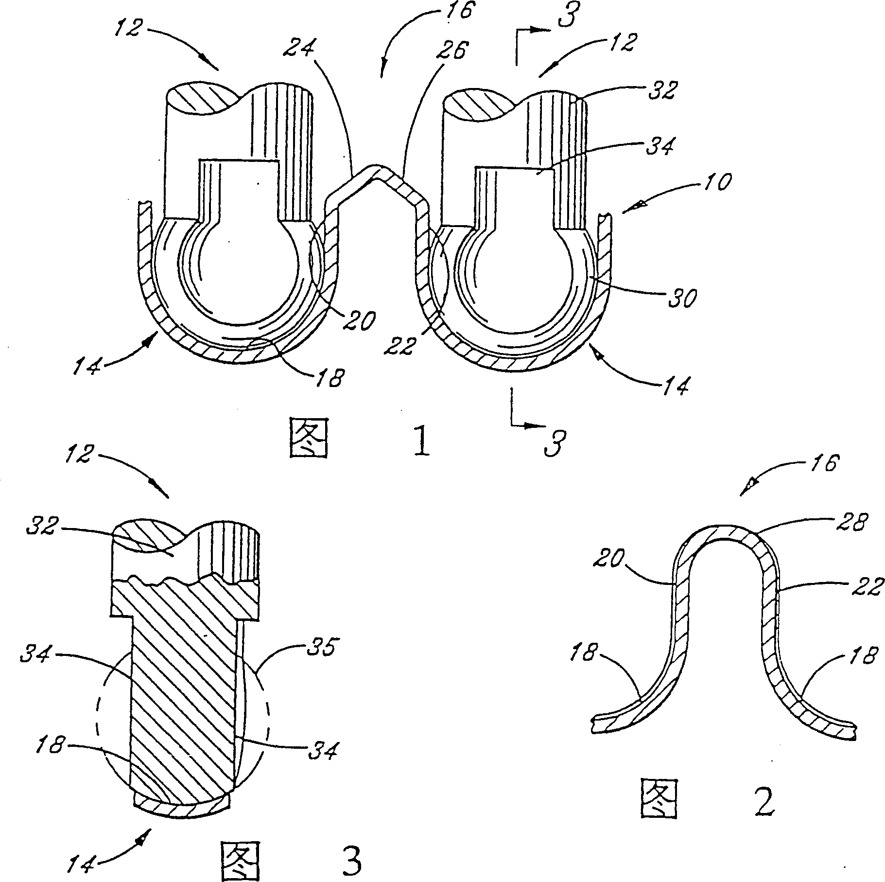
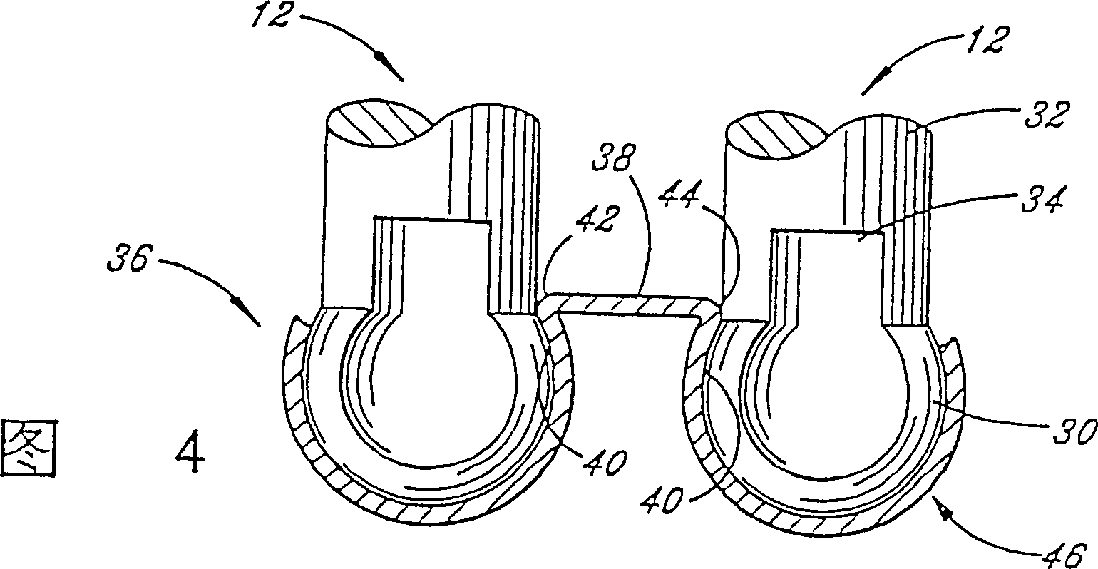
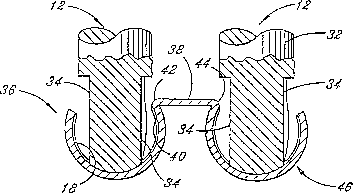
[0021] Referring now to the drawings, FIG. 1 shows a partially formed one-piece ball bearing cage 10 of the present invention and a mold including a movable anvil 12 that may finalize the one-piece ball bearing cage.

[0022] To partially form the ball bearing cage 10, a ring of flat sheet metal is first formed using any known forming method. For example, a flat ring like a "washer" can be extruded or punched from a wide flat strip. Alternatively, the edge-wound ("cure process") narrow strip of metal can be machined into segmented rings to form flat rings. The ends of the split ring may be welded or otherwise connected by butt, serrated or lapped parts, coined to a uniform thickness, and trimmed to size to make it a uniform part.

[0023] The flat thin ring is then deformed to form a partially formed ball bearing cage 10 with initial ball sockets 14 and bridges 16 between adjacent initial ball sockets 14 . The thin ring can be successively corrugated using conventional multi...


PUM


Abstract

A method of assembling a ball bearing assembly includes the steps of forming a one-piece metallic ball bearing cage having an initial configuration with ball pockets and bridge portions (16) between the ball pockets, at least a portion of the bridge portions (16) having a predetermined chordal length. The bearing balls (52) are positioned within an annulus between inner and outer bearing rings (68, 70), the bearing balls (52) being separated by an average chordal distance less than said predetermined chordal length and then the ball bearing cage is inserted into the annulus such that circumferential movement of the bearing balls (52) allows the bridge portions (16) of the ball bearing cage to pass between adjacent bearing balls (52) as the bearing balls (52) sequentially enter the ball pockets.

Description

technical field [0001] This invention relates generally to methods of assembling ball bearing assemblies and, more particularly, to methods of "stamping" or "snaking" bearing balls into ball bearing assemblies with a one-piece ball bearing cage. Background technique [0002] One common type of ball bearing cage consists of two pieces joined together by welding, riveting, or mechanical locking. Two-piece ball bearing cages require insertion of the two pieces of the cage from both sides of the ball bearing after the bearing balls are seated between the bearing rings. Welding is difficult because the arc may have to pass through the bearing balls, and riveting is also difficult because of the many small rivets that need to be inserted. Additional costs are incurred for the inspection and scrapping of defective bearing assemblies. [0003] An additional problem with two-piece ball bearing cages arises from their space requirements. Such ball bearing cages require sufficient c...

Claims


Application Information

Patent Timeline
Patent Type & Authority Patents(China)
IPC IPC(8): B23P13/00F16C33/41F16C33/42F16C43/04F16C43/06F16C43/08
CPCF16C43/08F16C33/425F16C33/41F16C19/06Y10T29/4965Y10T29/49679Y10T29/49686Y10T29/49691
Inventor R·L·阿林G·J·津肯
Owner TORRINGTON COMPANY
Learn More