A detachable installation frame for energy-saving building refrigeration and air conditioning
A technology for mounting racks and air conditioners, which is applied to the details of space heating and ventilation, household heating, lighting and heating equipment, etc. It can solve the problem of inability to quickly disassemble the air conditioner, and achieve the effect of quickly disassembling the air conditioner
- Summary
- Abstract
- Description
- Claims
- Application Information
AI Technical Summary
Problems solved by technology
Method used
Image
Examples
specific Embodiment approach 1
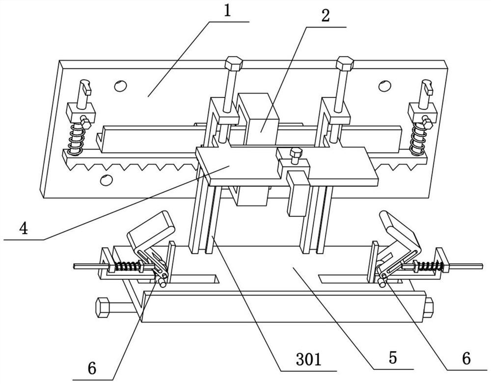
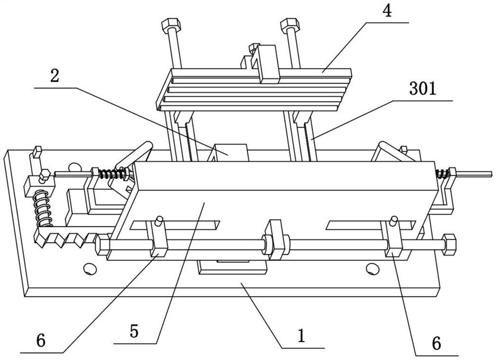
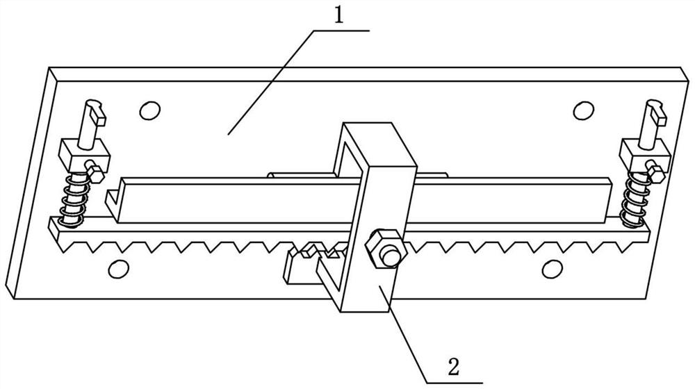
[0032] Combine below Figure 1-11 To illustrate this embodiment, the present invention relates to the field of energy-saving buildings, and more specifically to a detachable installation frame for energy-saving building refrigeration and air conditioning, including a wall panel 1, an L-shaped strip 101, a front panel 2, a connecting piece 202, and a panel 203 , the cross column 204 and the connecting flap 205, the present invention can realize the quick disassembly of the air conditioner.
[0033] The front side of the wall panel 1 is fixedly connected with an L-shaped strip 101, the upper end of the front plate 2 is fixedly connected with a connecting folded plate 205, and the rear portion of the connecting folded plate 205 is fixedly connected with a horizontal column 204, and the horizontal column 204 is inserted in the L The upper side of the bar 101 and the bottom of the front plate 2 are fixedly connected with a connecting piece 202 , and the rear end of the connecting p...
specific Embodiment approach 2
[0035] Combine below Figure 1-11To illustrate this embodiment, the detachable installation rack for energy-saving building refrigeration and air-conditioning also includes a stopper 102, a vertical slide bar 103, a fixing seat 104, a fastening screw I105 and a bead 106, and the left and right ends of the front side of the wall panel 1 are all fixed. The two fixed seats 104 are connected with the vertical sliding rod 103 vertically, the upper ends of the two vertical sliding rods 103 are fixedly connected with the stopper 102, and the lower ends of the two vertical sliding rods 103 are fixedly connected. Bead 106 is arranged, and the underside of bead 106 is evenly distributed with a plurality of triangular teeth, is all connected with fastening screw I105 by screw thread on two fixed bases 104, is all sleeved with compression spring I on two vertical slide bars 103, two Compression spring 1 is all positioned at the upper side of bead 106, and two compression springs 1 are res...
specific Embodiment approach 3
[0037] Combine below Figure 1-11 To illustrate this embodiment, the detachable installation rack for energy-saving building refrigeration and air-conditioning also includes a threaded shaft 201, a door-shaped plate 3, a vertical column 301 and a supporting plate 5, and the front middle part of the front plate 2 is fixedly connected with the threaded shaft 201, and the door-shaped The middle part of plate 3 is inserted on threaded shaft 201, and the front end of threaded shaft 201 is threadedly connected with nut, and nut is pressed on the front side of door-shaped plate 3, and the left and right ends of door-shaped plate 3 are all fixedly connected with upright post 301, two A supporting plate 5 is fixedly connected between the lower ends of the vertical columns 301. The air conditioner is fixed on the supporting plate 5, the door-shaped plate 3 can be rotated around the axis of the threaded shaft 201, the left and right inclination of the supporting plate 5 is adjusted, and ...
PUM
 Abstract
Description
Claims
Application Information
 - R&D
- Intellectual Property
- Life Sciences
- Materials
- Tech Scout
- Unparalleled Data Quality
- Higher Quality Content
- 60% Fewer Hallucinations
Browse by: Latest US Patents, China's latest patents, Technical Efficacy Thesaurus, Application Domain, Technology Topic, Popular Technical Reports.
© 2025 PatSnap. All rights reserved.Legal|Privacy policy|Modern Slavery Act Transparency Statement|Sitemap|About US| Contact US: help@patsnap.com


