Miniaturized multi-system multi-band fusion base station antenna

A base station antenna and multi-band technology, which is applied in the directions of antenna, antenna coupling, antenna parts, etc., can solve the problems affecting the application range of the antenna, the overall length of the antenna size, and the deterioration of the antenna pattern, so as to solve the problem of base station location, The effect of shortening the antenna size and passing the pattern index

Pending Publication Date: 2020-04-10
江苏泰科微通讯科技有限公司
View PDF0 Cites 4 Cited by
  • Summary
  • Abstract
  • Description
  • Claims
  • Application Information

AI Technical Summary

Problems solved by technology

[0005] In order to solve the problem that the overall size of the traditional multi-standard fusion antenna is too long or wide, which affects the application range of the antenna and easily leads to the deterioration of the antenna pattern, the present invention discloses a miniaturized multi-standard and multi-band fusion base station antenna. High-frequency radiation antenna array one, high-frequency radiation antenna array three, low-frequency radiation antenna array one, high-frequency radiation antenna array five, high-frequency radiation antenna array six, low-frequency radiation antenna array two, high-frequency radiation antenna array four and high-frequency radiation antenna arrays are arranged in parallel Frequency radiation antenna array 2, among them, the high and low frequency radiation array nested fusion technology greatly shortens the antenna size, effectively solves the problem of base station location selection, and improves the coverage of blind area signals in various complex scenarios

Method used


Image

  • Miniaturized multi-system multi-band fusion base station antenna
  • Miniaturized multi-system multi-band fusion base station antenna
  • Miniaturized multi-system multi-band fusion base station antenna

Examples


Embodiment Construction

[0030] The present invention is described in further detail now in conjunction with embodiment.

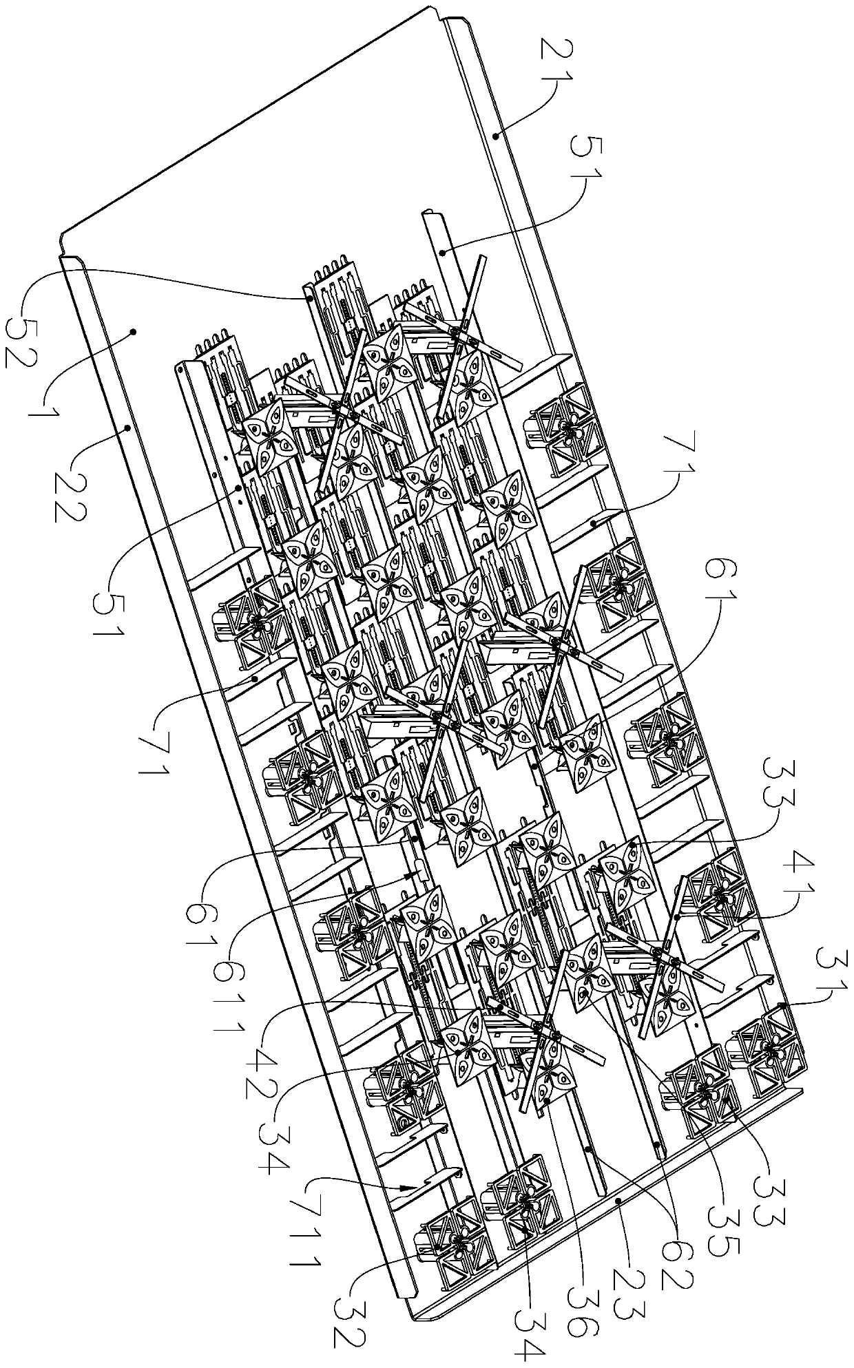
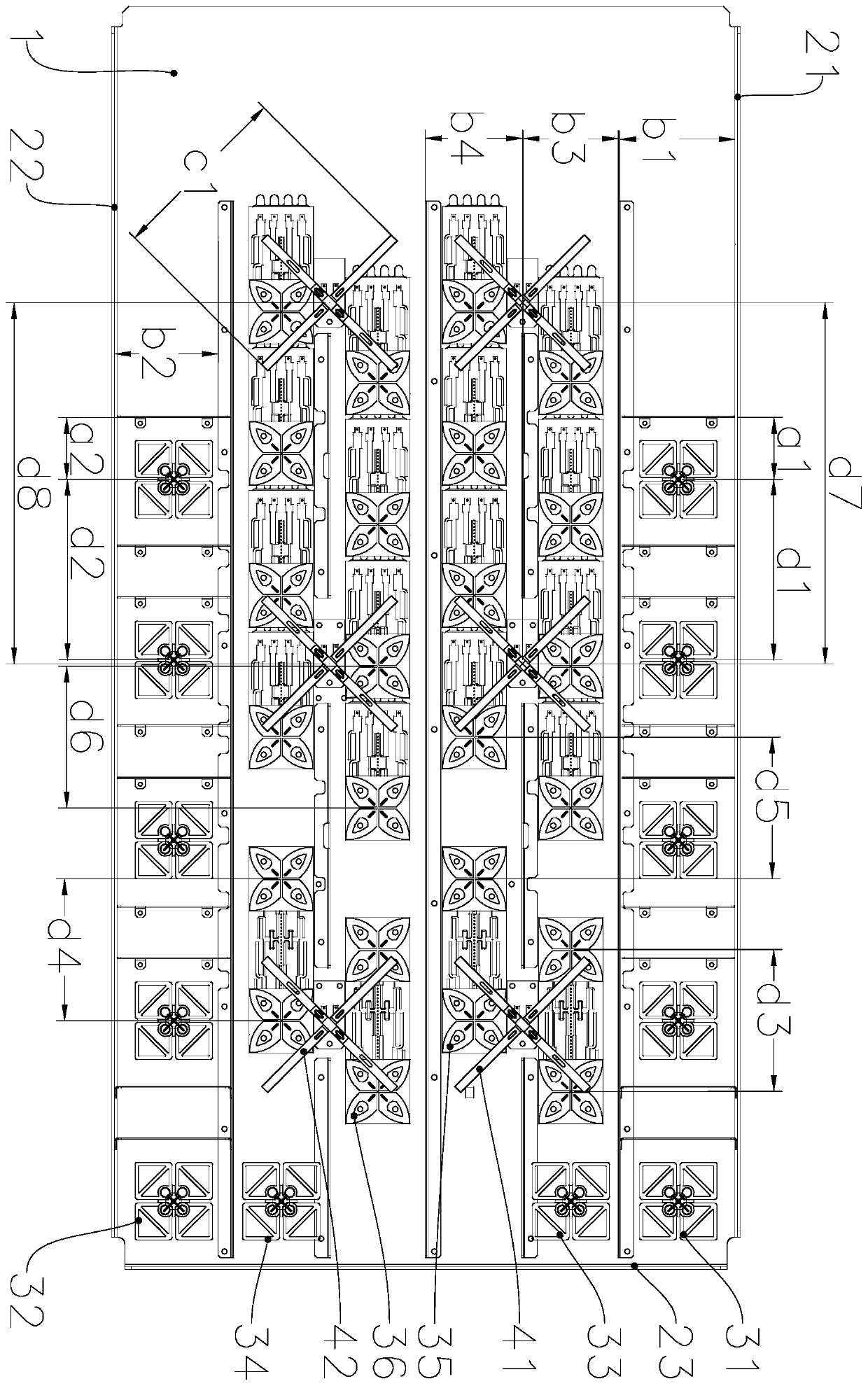
[0031]A miniaturized multi-standard multi-band fusion base station antenna, such as figure 1 As shown, a base plate 1 is included, a reflector one 21 and a reflector two 22 are respectively provided on the two long sides of the base plate 1, a reflector three 23 is provided on one short side of the base plate 1, and the base plate 1 There are high-frequency radiation antenna arrays 1, high-frequency radiation antenna array 3, low-frequency radiation antenna array 1, high-frequency radiation antenna array 5, and high-frequency radiation antenna array 6 arranged in sequence from reflector 1 to reflector 2 22. , low-frequency radiation antenna array two, high-frequency radiation antenna array four and high-frequency radiation antenna array two, the high-frequency radiation antenna array one, high-frequency radiation antenna array two, high-frequency radiation antenna array three, hig...


PUM


Abstract

The invention belongs to the technical field of base station antennas, and especially relates to a miniaturized multi-system multi-band fusion base station antenna. The antenna comprises a bottom plate, and a reflecting plate I and a reflecting plate II are respectively arranged on two long edges of the bottom plate; a reflecting plate III is arranged on one short edge of the bottom plate; the bottom plate is provided with a first high-frequency radiation antenna array, a third high-frequency radiation antenna array, a first low-frequency radiation antenna array, a fifth high-frequency radiation antenna array, a sixth high-frequency radiation antenna array, a second low-frequency radiation antenna array, a fourth high-frequency radiation antenna array and a second high-frequency radiationantenna array which are sequentially arranged in the direction from the first reflecting plate to the second reflecting plate. Each array comprises a plurality of high-frequency oscillators I, high-frequency oscillators II, high-frequency oscillators III, high-frequency oscillators IV, high-frequency oscillators V, high-frequency oscillators VI, low-frequency oscillators I and low-frequency oscillators II which are arrayed into a straight line; and first long isolation strips are arranged between the first high-frequency radiation antenna array and the third high-frequency radiation antenna array and between the fourth high-frequency radiation antenna array and the second high-frequency radiation antenna array.

Description

technical field [0001] The invention belongs to the technical field of base station antennas, and in particular relates to a miniaturized multi-standard and multi-band fusion base station antenna. Background technique [0002] With the in-depth construction of LTE networks, operators have put forward higher requirements for mobile signal coverage. Due to the complexity of my country's communication network, it can be predicted that the coexistence of multiple communication application standards will be maintained in the future. Currently, for mobile network signal coverage in venues, high-speed rail stations, and densely-built areas, operators not only need to face the challenge of increasing demand for network capacity, but also face the coexistence of multiple network standards such as 2G, 3G, 4G, and 5G. The problem of high operating costs in the environment. [0003] At present, due to the shortage of antenna resources, in order to make more effective use of site resou...

Claims


Application Information

Patent Timeline
IPC IPC(8): H01Q21/30H01Q21/29H01Q19/185H01Q1/52H01Q1/36H01Q1/24
CPCH01Q1/246H01Q1/36H01Q1/523H01Q19/185H01Q21/29H01Q21/30
Inventor 丁勇王德刘义成
Owner 江苏泰科微通讯科技有限公司
Why Eureka
Try Eureka