
Miniature omnidirectional microstrip antenna

A microstrip antenna and miniature technology, applied in the field of antennas, can solve the problems of low antenna radiation efficiency, increased production process, and inability to integrate, and achieve the effects of reducing antenna frequency, shortening antenna size, and wide application range

Active Publication Date: 2018-12-18
HANGZHOU DIANZI UNIV
View PDF9 Cites 0 Cited by
  • Summary
  • Abstract
  • Description
  • Claims
  • Application Information

AI Technical Summary

Problems solved by technology

However, due to the low operating frequency band and the large size of the antenna, it is very unfavorable for the miniaturization of the equipment
At the same time, this type of antenna cannot be integrated with the RF board, and needs to be processed, assembled and welded separately, thus increasing the production process
Microstrip antennas have the advantages of low profile, light weight, and easy integration. However, microstrip antennas in the 433MHz frequency band have not been widely used, mainly due to the corresponding design formulas, which determine the size of the radiation surface of microstrip antennas. The circuit is integrated, resulting in high cost of the antenna and large size of the whole device
At the same time, the microstrip antenna also has the disadvantages of high return loss, low antenna radiation efficiency, and narrow bandwidth.

Method used


Image

  • Miniature omnidirectional microstrip antenna
  • Miniature omnidirectional microstrip antenna
  • Miniature omnidirectional microstrip antenna

Examples


Embodiment Construction

[0029] The following will clearly and completely describe the technical solutions in the embodiments of the present invention with reference to the accompanying drawings in the embodiments of the present invention. Obviously, the described embodiments are only some, not all, embodiments of the present invention. Based on the embodiments of the present invention, all other embodiments obtained by persons of ordinary skill in the art without making creative efforts fall within the protection scope of the present invention.

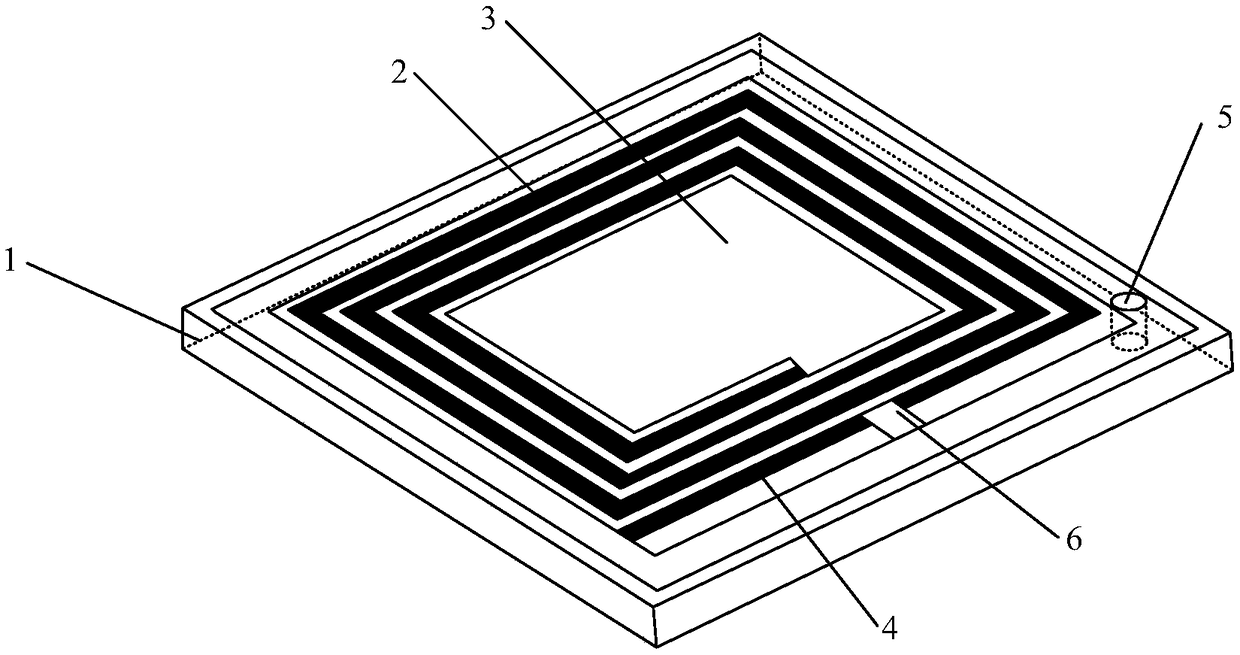
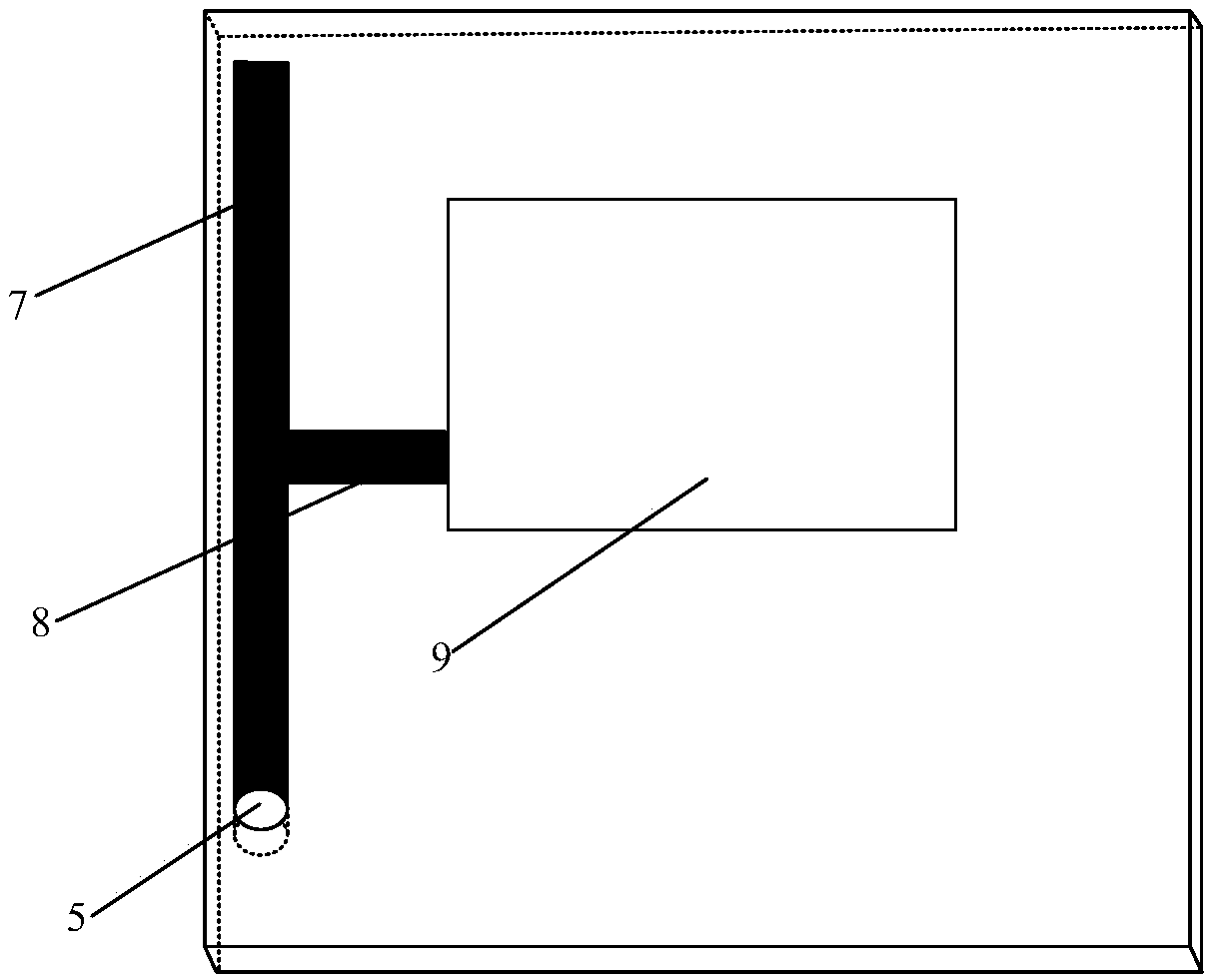
[0030] See figure 1 , 2 As shown, the miniature omnidirectional microstrip antenna shown in this embodiment includes a dielectric substrate (10), and an annular ground plate attached to one side of the dielectric substrate, a metal radiation layer and a metal ground layer on the other side.

[0031] The metal radiation layer includes a circular ground plate (1), a helical antenna arm (2), a radiation patch (3), a reverse extension line of the helical antenn...


PUM


Abstract

The invention discloses a miniature omnidirectional microstrip antenna. The antenna specifically comprises a dielectric substrate, a metal radiation layer attached to one side of the dielectric substrate and a metal layer attached to the other side of the dielectric substrate. A metal radiation lay is composed of a helical antenna and a radiation patch, and a metal lay is composed of a T-shaped microstrip line and a coupling patch. An annular ground plane is connected to the T-shaped microstrip line through a metal via. The novel antenna can maintain the omnidirectional radiation performance similar to monopole antenna, and the antenna section height is less than 0.01 wavelength. The antenna of the invention has the advantages of ultra-miniaturization, low profile, simple structure, stableperformance, easy integration and the like.

Description

technical field [0001] The invention relates to the technical field of antennas, in particular to a miniature omnidirectional microstrip antenna. Background technique [0002] In recent years, wireless communication systems have been widely used in various fields, and users can use wireless communication systems to transmit information without being limited by distance. The antenna is one of the important components in the field of wireless communication, and it has received more and more attention. With the development of wireless communication technology and electronic technology, the functions of wireless electronic products in daily life are becoming more and more powerful, while the size is becoming smaller, thinner and lighter. In the entire product design, the space and weight reserved for the antenna are limited, so it is necessary to design a miniaturized antenna for easy integration with the device circuit. [0003] Microstrip antenna is the most commonly used an...

Claims


Application Information

Patent Timeline
Patent Type & Authority Applications(China)
IPC IPC(8): H01Q1/36H01Q1/48H01Q1/50
CPCH01Q1/36H01Q1/48H01Q1/50
Inventor 罗国清代喜望金华燕张晓红
Owner HANGZHOU DIANZI UNIV
Learn More