
A method and device for generating batch cutting and placement graphics

A graphics generation and batch technology, applied in metal processing and other directions, can solve problems such as errors

Active Publication Date: 2022-03-22
DAMING HEAVY IND
View PDF7 Cites 0 Cited by
  • Summary
  • Abstract
  • Description
  • Claims
  • Application Information

AI Technical Summary

Problems solved by technology

sometimes mistakes

Method used


Image

  • A method and device for generating batch cutting and placement graphics
  • A method and device for generating batch cutting and placement graphics
  • A method and device for generating batch cutting and placement graphics

Examples


Embodiment

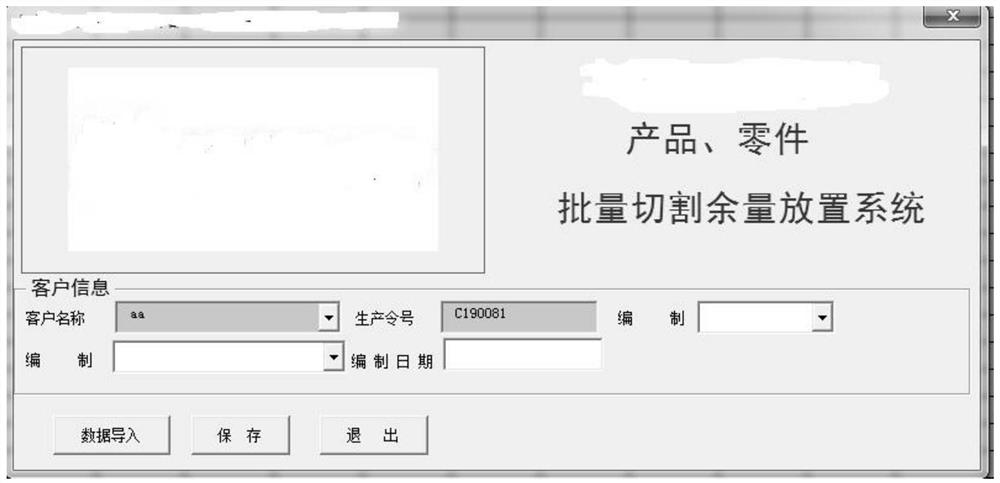
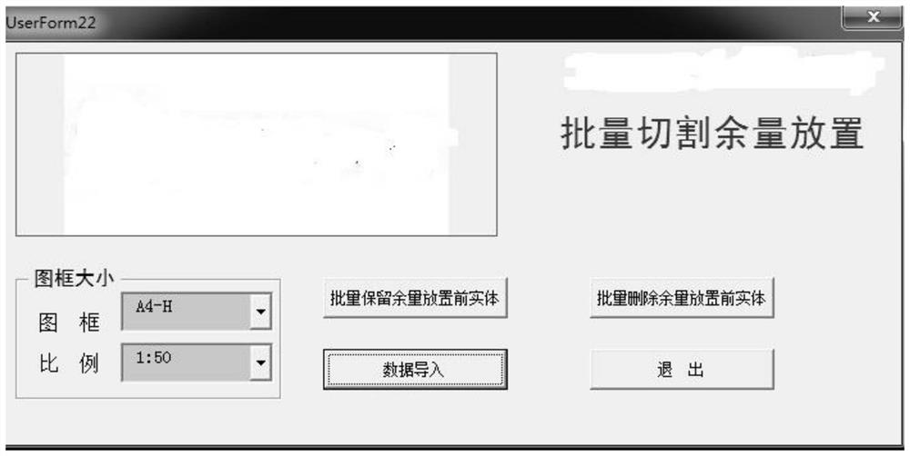
[0035] A batch cutting and placement graphics generation method for batch processing of cutting images, including a cutting diagram C file containing N parts to be cut and placed, an A file, and a B file, wherein the C file refers to a CAD file , the A file refers to the Excel process flow card, and the B file refers to the Excel cutting list. Such as figure 1 Shown is the main menu interface of the B file, such as figure 2 Shown is the menu interface of the C file.

[0036] First of all, the information of the N parts to be cut in the "Cutting Parts List" can be manually input by the staff, but it is cumbersome, but the company's parts information is stored in an Excel table, such as Figure 8 As shown, this embodiment named it "process flow card", therefore, this embodiment additionally provides a method for automatically inputting cutting information, the "process flow card" includes at least the codes and names of N parts , material, plate thickness, length and width, ...


PUM


Abstract

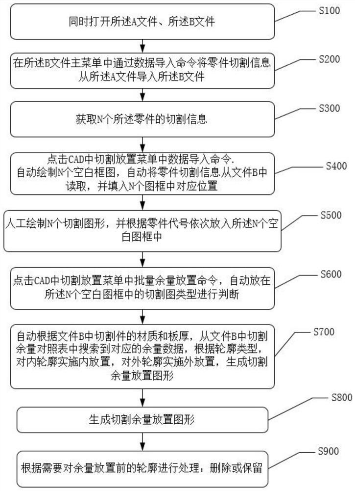
The invention discloses a batch cutting and placement graphics generation method and device, comprising the following steps: responding to the data import command of the main menu in the EXCEL cutting list, automatically importing the part cutting information of N parts into the list from the process flow card, Respond to the data import command in the corresponding menu of the CAD software, obtain the cutting information of N parts from the table, draw N blank frame diagrams and fill in the part cutting information in the frame, receive N cutting graphics input by the user, and respond to the user box Select the operation of cutting graphics, and judge the type of cutting graphics. If it is a region, it will break the region and convert it into a closed polyline contour; then judge the contour type; Search for the corresponding placement allowance in the cutting allowance comparison table in the table, place the inner contour inward, and place the outer contour outward; generate cutting placement graphics. Thereby improving the efficiency and accuracy of cutting and placement work.

Description

technical field [0001] The invention relates to the secondary development technology of EXCEL and AUTOCAD VBA, in particular to a method and device for batch cutting and placing graphics generation. Background technique [0002] At present, in the part cutting production, the staff must first establish the cutting part list, and then use the CAD software to place the margin on the cutting drawing provided by the technical department, and then go to the production workshop for cutting production . The specific operation is: place the outer contour of the cutting diagram outward, and place the inner contour inward. The placement amount needs to be manually judged according to the part and plate thickness. The work alone is not very difficult, but the staff have to process hundreds of cutting drawings every day, and click the inner and outer contours hundreds of times, which is a relatively heavy workload. This approach not only has low work efficiency, but is very easy to o...

Claims


Application Information

Patent Timeline
Patent Type & Authority Patents(China)
IPC IPC(8): B26D5/00
CPCB26D5/005B26D2005/002
Inventor 张文铭蒋俐松沈秋周磊
Owner DAMING HEAVY IND
Learn More