
Roller bit and construction method thereof
A roller cone bit and cone technology, which is applied in the direction of drill bits, drilling equipment, earthwork drilling and mining, etc., can solve the problems of prone to broken teeth, short service life of the cone, and disorderly grounding of teeth, etc., to achieve enhanced pressure bearing capacity, The effect of improving drilling efficiency and enhancing service life
- Summary
- Abstract
- Description
- Claims
- Application Information
AI Technical Summary
Problems solved by technology
Method used
Image

Examples
Embodiment 1
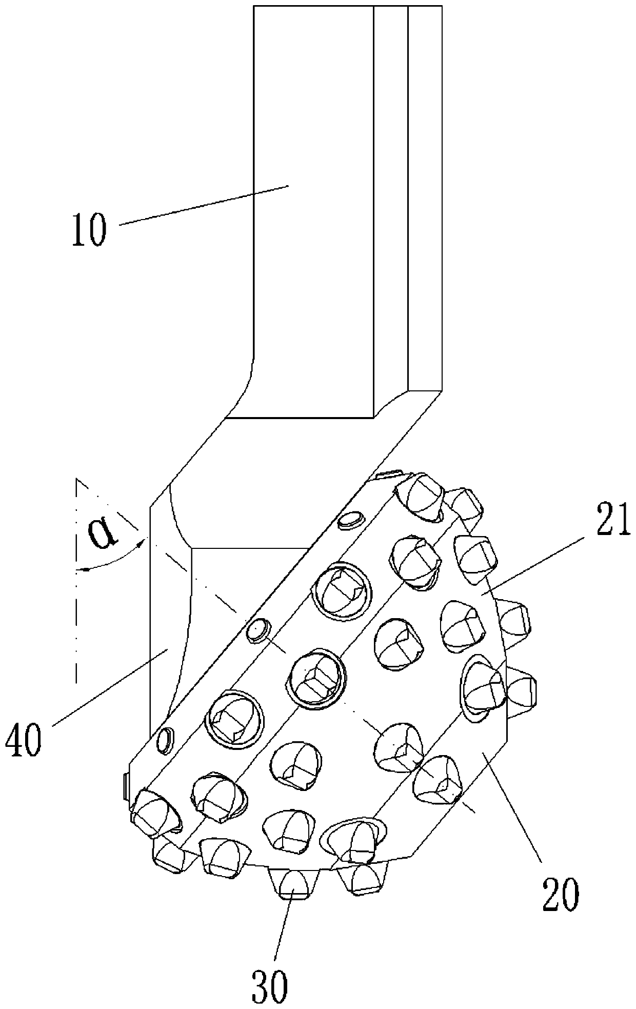
[0062] A single roller cone bit includes a bit body 10, a roller cone 20 and multiple rows of teeth 30.
[0063] The roller cone 20 is connected to the drill body 10 through an offset palm journal 40 and is arranged to be rotatable relative to the drill body 10, wherein the angle between the axis of the palm journal 40 and the feed axis of the drill body 10 is α is 40°-60°, for example figure 2 In the case where the included angle α is 50°, when the drill bit is working, the bit body 10 rotates to drive the cone 20 to rotate around its axis, and the cone 20 will also roll around its own axis.
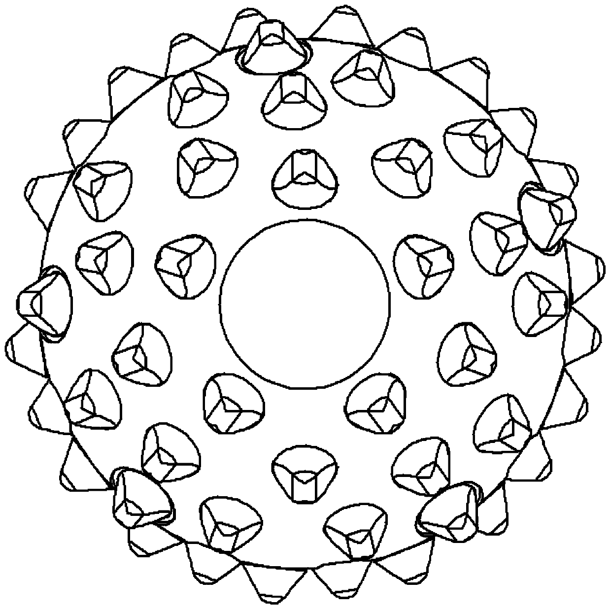
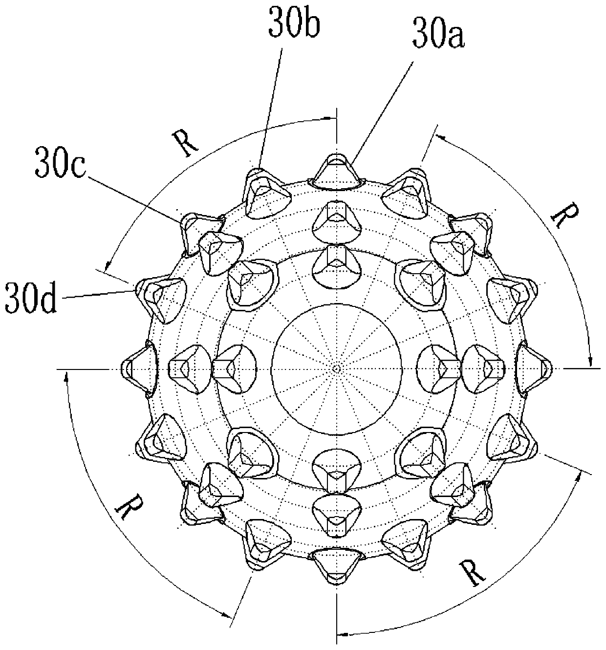
[0064] The cone 20 is in the shape of a truncated cone as a whole, and its generatrix is an arc. A conical tooth surface 21 is formed on the outer peripheral wall of the cone 20. Multiple sets of teeth 30 are arranged on different meridians of the conical tooth surface 21. Each Each row of teeth 30 contains more than two teeth, so as to avoid the occurrence of a single tooth landing...
Embodiment 2
[0075] A combined roller cone bit, including two roller cone bits 50, a mounting base 60 and an impact device 70, wherein the structure of the roller cone bit 50 and the distribution of teeth are shown in detail in Embodiment 1, and will not be repeated here. Only to introduce the cooperative use structure of the roller cone bit 50 and the impact device 70, and in the single roller cone bit 50, the impact device 70 can still be used. For details, please refer to the following structure:
[0076] Such as Figure 6 As shown, the impact device 70 includes a movable shaft 71 , an energy storage element 72 , a balancing pressure head 73 (balance element) and a support 74 .
[0077] Two roller cone bits 50 are oppositely installed on the mounting base 60, and the bit body 10 in the roller cone bit 50 is parallel to the axis of the movable shaft 71, and the movable shaft 71 is fixedly connected with the mounting base 60, and the movable shaft 71 can expand and contract along the fee...
Embodiment 3
[0086] A method for constructing teeth on a cone, for forming the cone bit of the structure in Example 1, which includes arranging the teeth on the cone in the following manner:
[0087] Multiple sets of rows of teeth 30 are arranged along the radial line of the cone 20, and the multiple sets of rows of teeth 30 that land sequentially produce a periodic drop, and during the sequential landing of adjacent rows of teeth 30, the center of the cone 20 can generate a gap along its radial direction. The impact displacement in the direction, and the impact displacement value generated by it is above 0.6mm.
[0088] Among them, a preferred size of the gear cone is: the diameter of the cone bottom (large end) is 128mm, the diameter of the cone top (small end) is 44mm, the overall height is 80mm, and the radius of the arc-shaped generatrix is 145mm. The included angle between the axis of 40 and the feed axis of the drill body 10 is α and is 50°. By setting sixteen groups of rows of te...
PUM
| Property | Measurement | Unit |
|---|---|---|
| Diameter | aaaaa | aaaaa |
| Diameter | aaaaa | aaaaa |
| Height | aaaaa | aaaaa |
Abstract
Description
Claims
Application Information