Card tray plugging mechanism and electronic equipment

A technology for plugging and unplugging mechanisms and electronic equipment, applied to circuits, electrical components, coupling devices, etc., can solve the problems of increasing the difficulty of waterproofing electronic equipment, and achieve the effect of reducing the difficulty of waterproofing

Active Publication Date: 2021-03-23
VIVO MOBILE COMM CO LTD
View PDF8 Cites 0 Cited by
  • Summary
  • Abstract
  • Description
  • Claims
  • Application Information

AI Technical Summary

Problems solved by technology

[0005] In view of this, the embodiment of the present invention provides a card tray insertion mechanism and electronic equipment to solve the problem in the prior art that the thimble socket provided in the card tray insertion mechanism increases the difficulty of waterproofing the electronic equipment

Method used


Image

  • Card tray plugging mechanism and electronic equipment
  • Card tray plugging mechanism and electronic equipment

Examples


Embodiment Construction

[0016] The following will clearly and completely describe the technical solutions in the embodiments of the present invention with reference to the accompanying drawings in the embodiments of the present invention. Obviously, the described embodiments are only some, not all, embodiments of the present invention. Based on the embodiments of the present invention, all other embodiments obtained by persons of ordinary skill in the art without making creative efforts belong to the protection scope of the present invention.

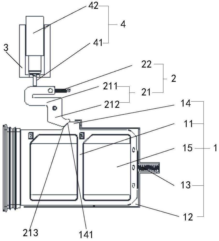
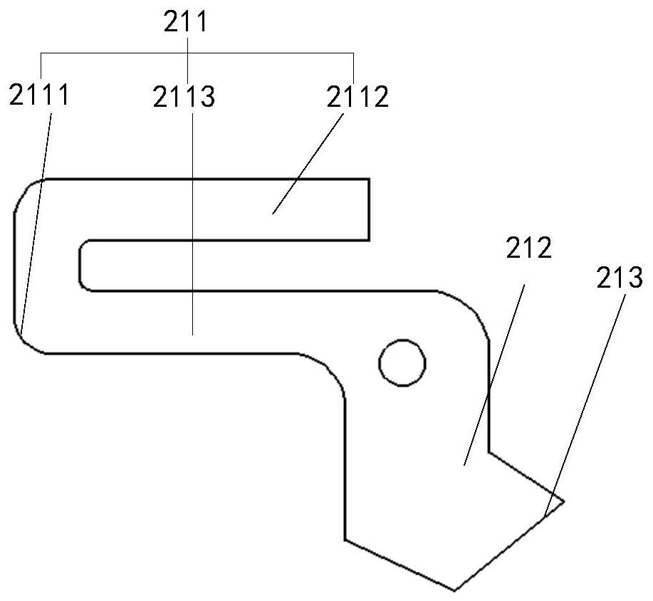
[0017] The card tray insertion and withdrawal mechanism of the embodiment of the present invention will be described in detail below with reference to the accompanying drawings. figure 1 It is a structural schematic diagram of the card tray insertion and withdrawal mechanism of the embodiment of the present invention. Such as figure 1 As shown, the card tray insertion mechanism is arranged on the main board included in the electronic equipment. The card tray ...


PUM


Abstract

The embodiment of the invention provides a card holder plugging mechanism and electronic equipment. The card holder plugging mechanism comprises a card holder assembly, the card holder assembly comprises a card holder, a card seat and a first elastic element, the card seat is fixed on the main board, the card holder is plugged on the card seat, and one end of the first elastic element is fixed onthe card seat, and one side edge of the card holder is provided with a limiting part; a lever assembly comprises a transmission lever and a second elastic element, the transmission lever is hinged tothe main board, the hinge point is the fulcrum of the transmission lever, one end of the second elastic element is fixedly connected with the main board, and the other end of the second elastic element is fixedly connected with the end of the transmission lever; and the bottom of a socket is provided with a through hole. When the first elastic element is in a compressed state, the other end of thefirst elastic element is contacted with the card holder, and the second end of the transmission lever is pressed against and contacted with the limiting part. Thus, with the help of the through holeformed in the bottom of the card seat, the card holder assembly can be controlled by the pin, the card holder can be taken out, and the waterproof difficulty of the electronic equipment is reduced.

Description

technical field [0001] The invention relates to the technical field of electronic equipment, in particular to a card holder insertion mechanism and electronic equipment. Background technique [0002] With the advancement of technology and the continuous improvement of consumer demand, the appearance of electronic equipment is becoming more and more simple. With the simplification of the appearance of the electronic equipment, the external opening design of the electronic equipment becomes less and less. [0003] At present, the card tray of the electronic device usually adopts a plug-in design to realize the pick-and-place of the SIM (Subscriber Identification Module) card. The main implementation method is to open a thimble hole on the card tray or the frame on one side of the card tray, and insert the thimble into the thimble hole to trigger the ejection part of the tray, and then make the tray eject. [0004] However, since the thimble hole is provided on the card tray ...

Claims


Application Information

Patent Timeline
Patent Type & Authority Patents(China)
IPC IPC(8): H01R13/502H01R13/52H01R13/627H01R13/629
CPCH01R13/502H01R13/5202H01R13/627H01R13/629
Inventor 杨鹏博
Owner VIVO MOBILE COMM CO LTD
Why Eureka
Try Eureka