Main power supply and standby power supply switching circuit

A technology for switching circuits, main and backup power supplies, applied in circuit devices, emergency power supply arrangements, high-efficiency power electronic conversion, etc., can solve problems such as danger, spark generation, breakdown of support capacitors, etc. The effect of small inrush current

Inactive Publication Date: 2020-04-17
WUHAN MARINE ELECTRIC PROPULSION RES INST CHINA SHIPBUILDING IND CORP NO 712 INST
View PDF6 Cites 2 Cited by
  • Summary
  • Abstract
  • Description
  • Claims
  • Application Information

AI Technical Summary

Problems solved by technology

[0004] First, it is difficult to realize the priority selection of the main power supply and the automatic switching of the main and backup power supplies; the second is that the opening and closing time of the circuit breaker is relatively long, generally at the ms level, so that the output cannot be maintained during the power supply switching process. Uninterrupted; thirdly, during the power switching process, due to the large voltage difference between the main power supply and the backup power supply, the impact current on the supporting capacitor is relatively large, so the supporting capacitor may be broken down; fourthly, the power consumption of the circuit breaker during the switching process Larger and sparks will be generated during reed switching, which is dangerous

Method used


Image

  • Main power supply and standby power supply switching circuit
  • Main power supply and standby power supply switching circuit

Examples


Embodiment Construction

[0013] The present invention will be described in further detail below by taking a ship application as an example in conjunction with the accompanying drawings.

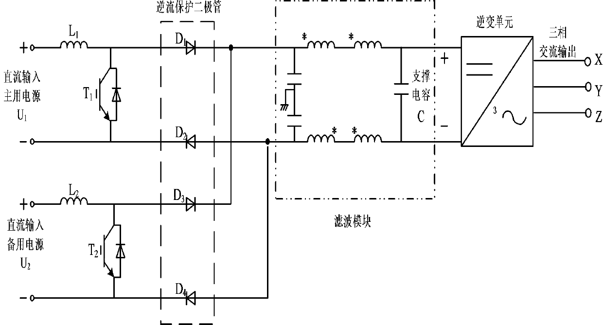
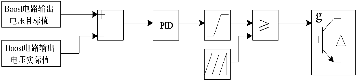
[0014] refer to figure 1 As shown, the main and backup power inputs of the present invention are powered by ship rectifier generators, and the power supply voltage is 350V to 640V. Two Boost chopper circuits are used to boost the main and backup power inputs to 660V and 650V respectively; The first Boost chopper circuit and the second Boost chopper circuit adopt closed-loop PID control. The first Boost chopper circuit is composed of a boost inductor L1, a switch tube T1 and its anti-parallel diode. The voltage chopper circuit is composed of boost inductor L2, switch tube T2 and its anti-parallel diode. The control system block diagram refers to figure 2 shown.

[0015] When the main power supply and the backup power supply exist at the same time, since the output voltage of the Boost branch where the main power su...


PUM


Abstract

The invention discloses a main power supply and standby power supply switching circuit, which comprises a direct-current input main power supply U1 and a direct-current input standby power supply U2 for supplying power to a ship rectification generator, a first Boost chopper circuit for boosting the direct-current input main power supply U1, a second Boost chopper circuit for boosting the direct-current input standby power supply U2, counter-current protection diodes D1-D4, a filtering module and an inversion unit for converting direct-current input into three-phase alternating-current output,wherein the two Boost chopper circuits adopt closed-loop PID control, and the Boost branch output voltage U1' of the first Boost chopper circuit is controlled to be 2-10 V larger than the Boost branch output voltage U2' of the second Boost chopper circuit. According to the main power supply and standby power supply switching circuit, priority selection of main power supply branches and automaticswitching between main and standby power supplies can be realized; and compared with the traditional power supply switching circuit adopting a circuit breaker and a relay, the main power supply and standby power supply switching of the invention adopts a power electronic device to switch, has the extremely short switching time of only [mu]s, can ensure the uninterrupted output of the inverter sidein the power supply switching process, and achieves seamless switching.

Description

technical field [0001] The invention belongs to the field of power electronics, and in particular relates to a main and standby power switching circuit. Background technique [0002] With the development of power electronics technology, the reliability and stability of power supply for power electronics equipment are becoming more and more stringent. For example, power electronic equipment such as frequency converters and inverter power supplies are required to be powered by two main and backup power sources to ensure safe and reliable power supply. [0003] The traditional main and backup power switching circuit adopts circuit breakers and relays, which have many disadvantages: [0004] First, it is difficult to realize the priority selection of the main power supply and the automatic switching between the main and backup power supplies; the second is that the opening and closing time of the circuit breaker is relatively long, generally at the ms level, so that the output ...

Claims


Application Information

Patent Timeline
Patent Type & Authority Applications(China)
IPC IPC(8): H02J9/06H02M1/12
CPCH02J9/062H02M1/12H02M1/123Y02B70/10Y02B70/30Y04S20/20
Inventor 谢佩韦刘成浩李争光李成阳何忠祥
Owner WUHAN MARINE ELECTRIC PROPULSION RES INST CHINA SHIPBUILDING IND CORP NO 712 INST
Why Eureka
Try Eureka