Hydraulic valve for differential loop and hydraulic differential loop

A hydraulic valve and circuit technology, which is applied in the direction of fluid pressure actuators, servo motors, servo motor components, etc., can solve the problems of high application cost and complexity, and achieve the effect of simplifying the structure and reducing the use

Inactive Publication Date: 2018-06-19
邵立坤
View PDF12 Cites 0 Cited by
  • Summary
  • Abstract
  • Description
  • Claims
  • Application Information

AI Technical Summary

Problems solved by technology

Although this invention can realize the conversion of hydraulic cylinder fast forward and working conditions, it is relatively complicated, including too many valve parts and electronic detection and control components, and the application cost is relatively high

Method used


Image

  • Hydraulic valve for differential loop and hydraulic differential loop
  • Hydraulic valve for differential loop and hydraulic differential loop

Examples


Embodiment Construction

[0027] In order to make the technical solutions and advantages of the present invention clearer, the exemplary embodiments of the present invention will be further described in detail below in conjunction with the accompanying drawings. Apparently, the described embodiments are only a part of the embodiments of the present invention, and are not exhaustive of all the embodiments. And in the case of no conflict, the embodiments and the features in the embodiments of the present invention can be combined with each other.

[0028] Embodiments of the present invention propose a hydraulic valve for a differential circuit, which will be described below.

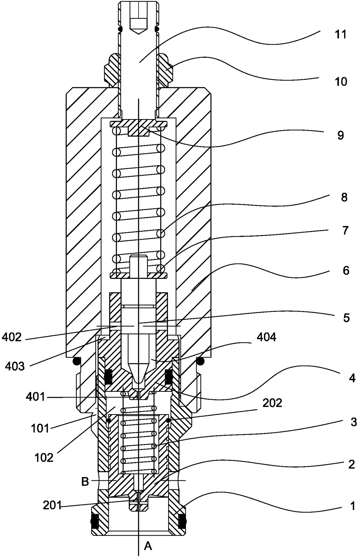
[0029] figure 1 One embodiment of a hydraulic valve 17 for a differential circuit according to the invention is shown. In this embodiment, the hydraulic valve 17 for a differential circuit of the present invention mainly includes: a valve body 1 , a main valve core 2 , a pilot valve sleeve 4 , a pilot valve core 5 and a screw sle...


PUM


Abstract

The invention provides a hydraulic valve for a differential loop and the hydraulic differential loop. The hydraulic valve for the differential loop comprises a valve body, a main valve element, a pilot valve sleeve, a pilot valve element and a thread sleeve assembly, wherein the valve body is provided with an oil port A and an oil port B, the main valve element is connected into the valve body, the main valve element is provided with a first damping channel, the pilot valve sleeve is connected into the valve body and connected with the main valve element through a first elastic piece, a control cavity is formed between the pilot valve sleeve and the main valve element, the pilot valve sleeve is provided with a pilot valve element cavity, a through-flow hole and a second damping channel communicating with the control cavity, the pilot valve element is movably connected into the pilot valve element cavity, one end of the pilot valve element plugs a valve opening, communicating with the second damping channel, of the pilot valve sleeve, the middle portion of the pilot valve element plugs the through-flow hole, the thread sleeve assembly is connected to the outer side of the pilot valve sleeve in a sleeving manner and connected with the valve body, the thread sleeve assembly is provided with a thread sleeve channel communicating with the oil port B, and the thread sleeve assembly is connected with the other end of the pilot valve element. The hydraulic valve for the differential loop simplifies the structure of the differential loop, reduces use of a controller and provides backpressure for the feeding working condition.

Description

technical field [0001] The invention relates to the technical field of valves, in particular to a hydraulic valve for a differential circuit and a hydraulic differential circuit. Background technique [0002] As a basic hydraulic control circuit, the differential hydraulic cylinder control circuit has been widely used in the fields of industrial hydraulics and engineering machinery. The essence of the differential control circuit of the single-piston rod hydraulic cylinder is to return the liquid discharged from the rod chamber of the hydraulic cylinder to the rodless chamber of the hydraulic cylinder, thereby increasing the flow into the rodless chamber and correspondingly increasing the extension speed of the piston rod. It can flexibly meet the working requirements of high thrust and low speed and low thrust and high speed. The differential circuit control is divided into two working conditions: fast forward and working forward. In the fast forward working condition, the...

Claims


Application Information

Patent Timeline
IPC IPC(8): F15B11/024F15B13/042
CPCF15B11/024F15B13/0402F15B2013/041
Inventor 邵立坤
Owner 邵立坤
Why Eureka
Try Eureka