Laser peak power testing method and device
A technology of peak power and test method, applied in the field of laser peak power test method and device, can solve the problem of inability to accurately calculate the peak power of the laser, and achieve the effect of simplifying the test process
- Summary
- Abstract
- Description
- Claims
- Application Information
AI Technical Summary
Problems solved by technology
Method used
Image

Examples
Embodiment 1
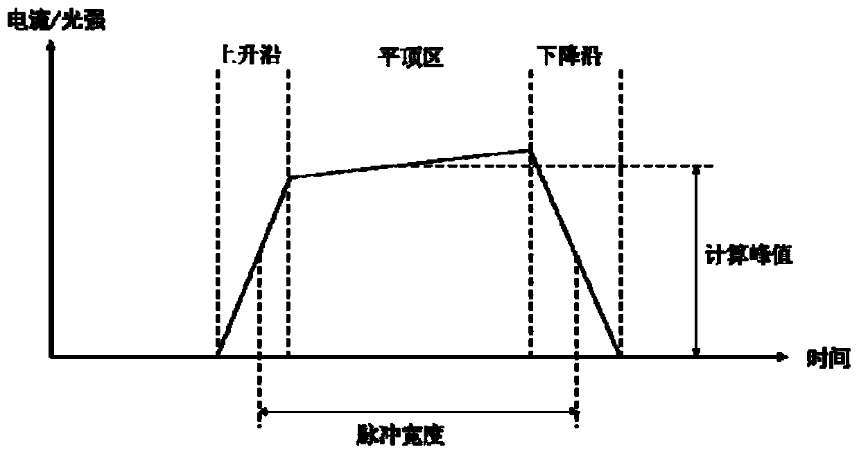
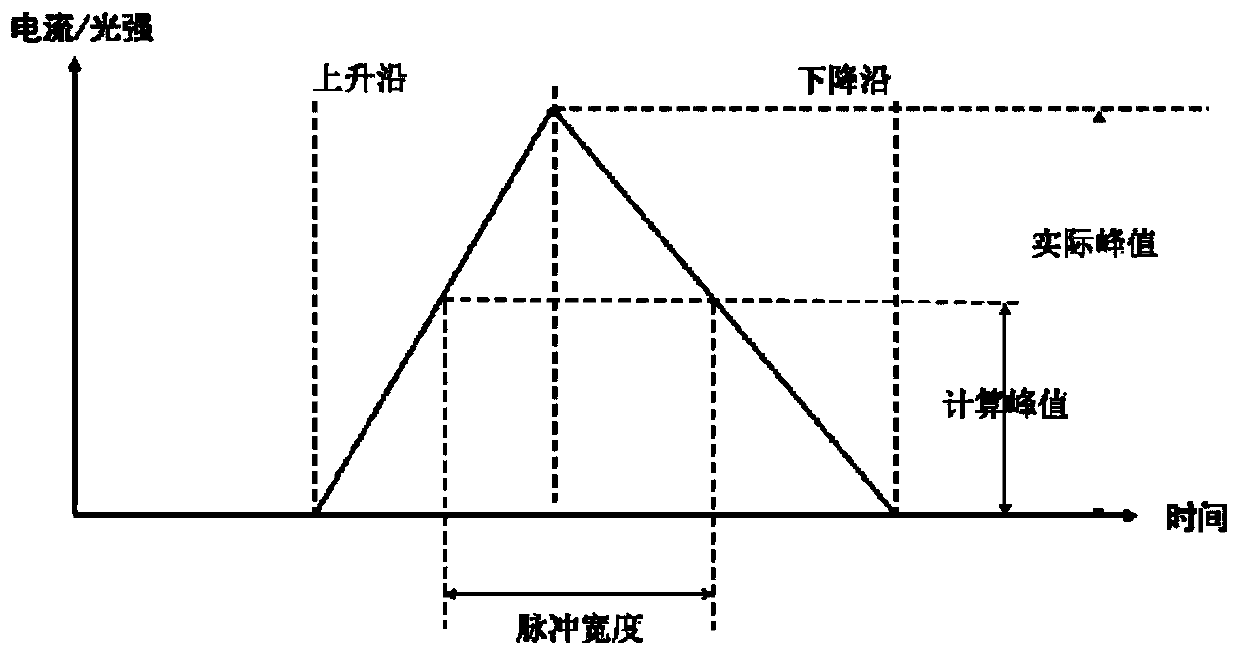
[0031] When testing the peak optical power of a pulsed or quasi-continuous laser, the average optical power P of the laser is generally measured with a thermal pile power meter avi , then measure the pulse waveform of the output light and calculate the pulse width t wp and repetition frequency f p , or measure the pulse width t of the input current pulse with a current gun and an oscilloscope wi and repetition frequency f i , the product of pulse width and repetition frequency to get the duty cycle, divide the average optical power by the duty cycle to get the peak power, the calculation formula is: or, When the input drive pulse current and laser signal are ideal square waves, the accurate peak power can be calculated by the above measurement methods, but in actual situations, the current generally cannot present an ideal square wave, resulting in the laser signal not being an ideal square wave. Therefore, in this method, the peak power of the laser can only be roughly ...
Embodiment 2
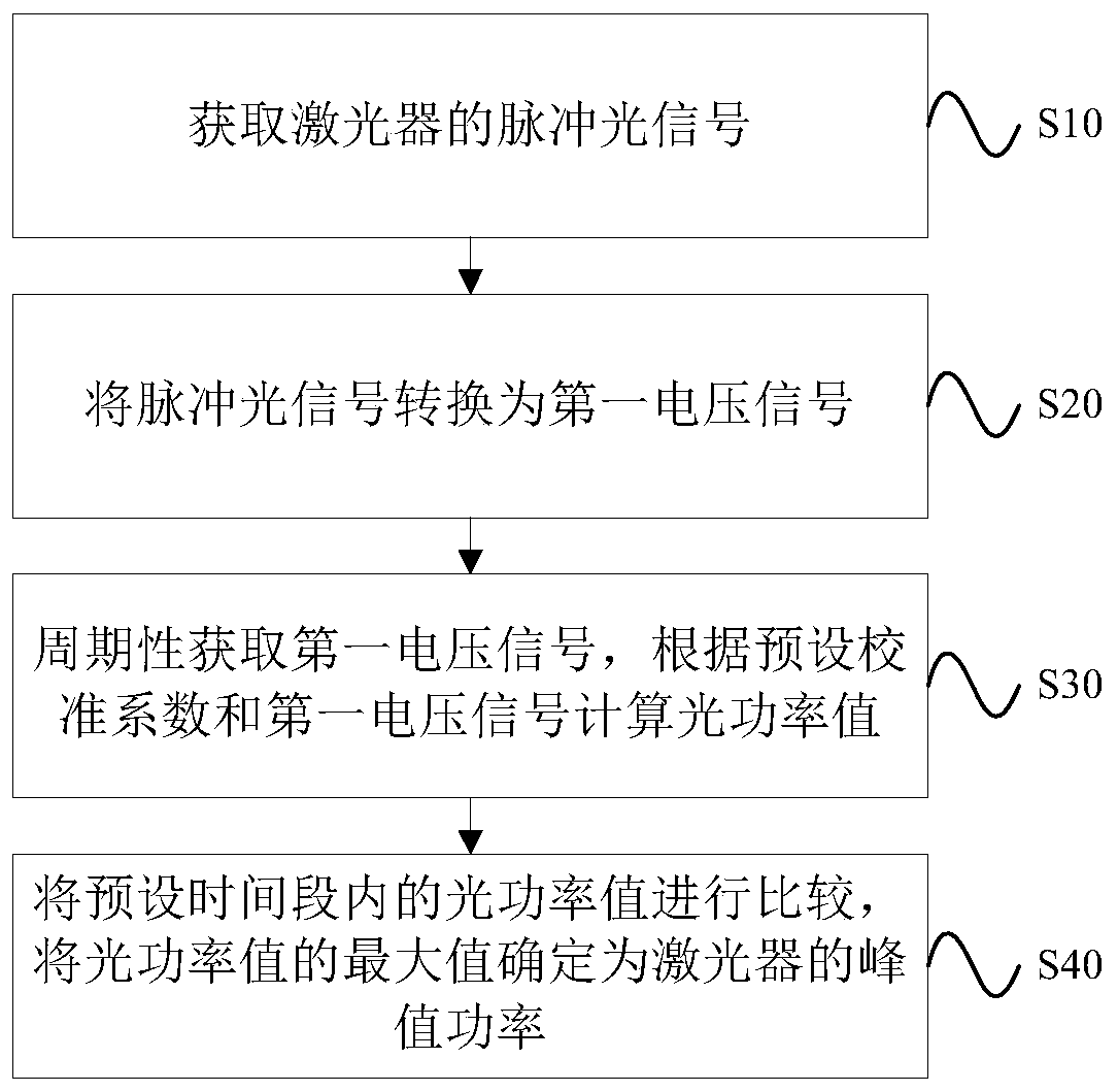
[0049] This embodiment provides a laser peak power testing device, such as Figure 9 shown, including:
[0050] Integrating sphere 1 is used to obtain the pulse laser signal that laser device 5 sends, and in a specific embodiment, the size of integrating sphere 1 can be selected according to actual needs, and in the embodiment of the present invention, the diameter of integrating sphere 1 selected is 250mm, Caliber 50mm. For a detailed description of the pulsed laser signal, refer to the description of step S10 in Embodiment 1 above.
[0051] Detector 2 is used to convert the pulsed laser signal into the first voltage signal. In a specific embodiment, the selection of detector 2 can be selected according to actual needs. The detector 2 selected in the embodiment of the present invention is ThorlabsPDA100A Model, Si photodetector 2 with a detection wavelength range of 340nm-1100nm.
[0052] The data acquisition card 3 is used to periodically acquire the first voltage signal,...
PUM
 Abstract
Description
Claims
Application Information
 - R&D Engineer
- R&D Manager
- IP Professional
- Industry Leading Data Capabilities
- Powerful AI technology
- Patent DNA Extraction
Browse by: Latest US Patents, China's latest patents, Technical Efficacy Thesaurus, Application Domain, Technology Topic.
© 2024 PatSnap. All rights reserved.Legal|Privacy policy|Modern Slavery Act Transparency Statement|Sitemap