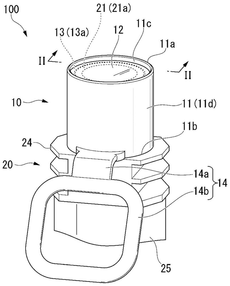
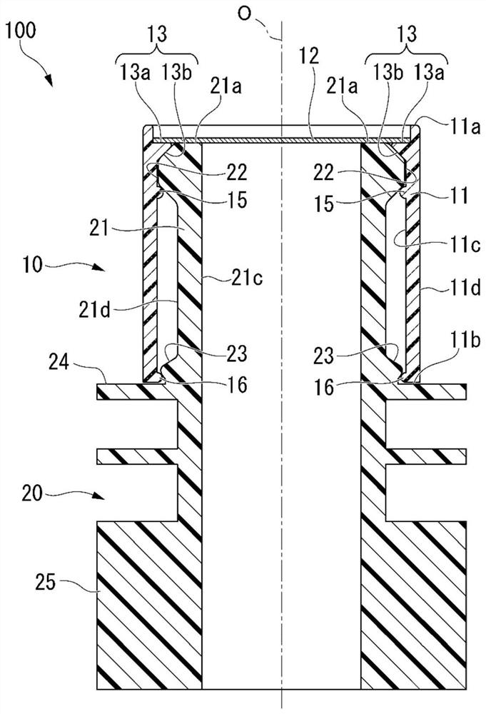
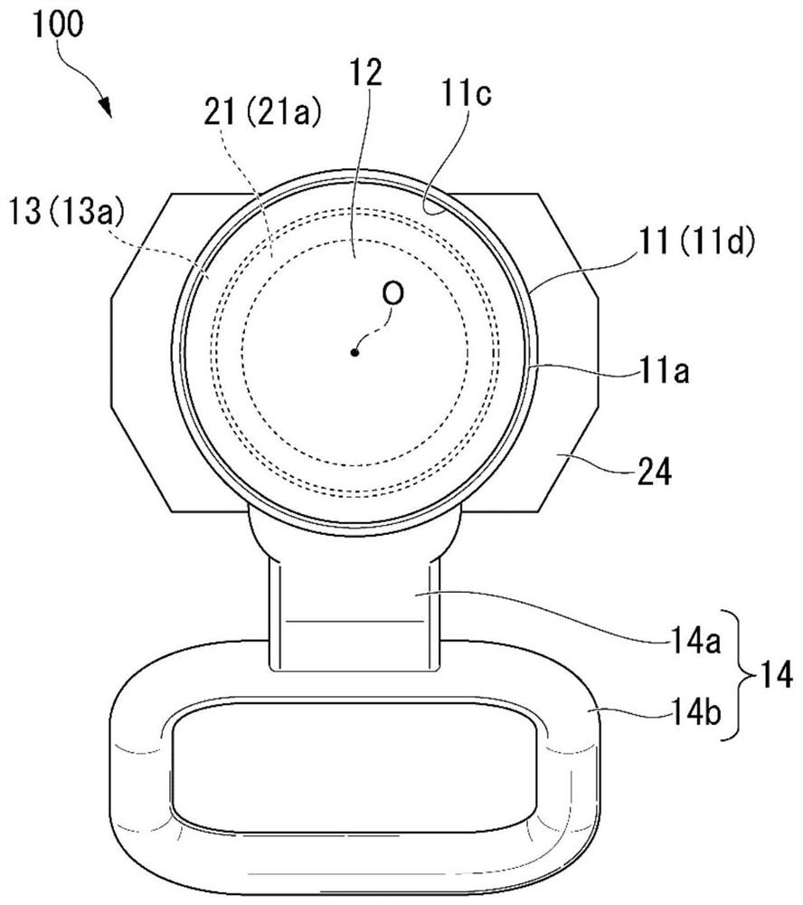
Spout caps, spouts and containers with spouts
A spout and container technology, which is applied in spout caps, spouts, containers with spouts, and containers with spouts. It can solve the problems of difficulty in peeling off, labor and time, and difficulty in pinching the sealing film, and achieve a reliable and airtight effect.
- Summary
- Abstract
- Description
- Claims
- Application Information
AI Technical Summary
Problems solved by technology
Method used
Image
Examples
Deformed example 1
[0117] Image 6 It is a perspective view showing the nozzle 200 of Modification 1 of the present embodiment. Such as Image 6 As shown, the spout 200 includes a spout body 40 and a spout cap 30 mounted on the spout body 40 . The spout 200 includes a rotation preventing mechanism 50 that prevents relative rotation of the spout cap 30 and the spout body 40 . Other structures are the same as those of the nozzle 100 described above.
[0118] The rotation preventing mechanism 50 includes a rotation preventing concave portion 50 a provided on the base end side of the body portion 31 of the spout cap 30 and a rotation preventing convex portion 50 b standing upright on the front end side of the flange portion 44 of the spout body 40 . In the spout main body 40 , a container mounting portion 45 is provided on the base end side of the flange portion 44 .
[0119] Such as Image 6 As shown, a part of the base end side of the body part 31 is notched to form a rotation preventing conc...
Deformed example 2
[0128] Figure 7 It is a perspective view showing a nozzle 300 according to Modification 2 of the present embodiment. Such as Figure 7 As shown, the spout 300 includes a spout body 20 and a spout cap 60 installed on the spout body 20 . The spout cap 60 of the spout 300 is provided with a weakened portion 62 that breaks when the spout cap 60 is detached from the spout body 20 . Other structures are the same as those of the nozzle 100 described above.
[0129] The weakened portion 62 is provided on the trunk portion 61 . Such as Figure 7 As shown, the weakened portion 62 sandwiches the holding portion 14 and is respectively provided on both sides.
[0130] Each weakened portion 62 starts from the base end of the trunk portion 61 and advances linearly toward the front end of the trunk portion 61 , near the top of the trunk portion 61 , so as to extend from the grasping portion 14 in the circumferential direction of the trunk portion 61 . Separate the direction of the forw...
Deformed example 3
[0136] Figure 8 It is a perspective view showing a nozzle 400 according to Modification 3 of the present embodiment. Such as Figure 8 As shown, the spout 400 includes a spout body 20 and a spout cap 70 installed on the spout body 20 . The nozzle cap 70 of the nozzle 400 is provided with a cover body 72 disposed on the front end 71 a of the trunk part 71 . Other structures are the same as those of the nozzle 100 described above.
[0137] exist Figure 8 In , a part of the cover body 72 is shown broken. The cover body 72 is joined to the front end 71 a of the body part 71 and provided so as to cover the sealing film 12 . The material of the cover body 72 may be the same as that of the trunk part 71 (trunk part 11 ).
[0138] After the sealing film 12 is thermally bonded to the mouth portion 21 of the spout body 20 , the lid body 72 can be bonded to the front end 71 a of the body portion 71 .
[0139] In addition, when the sealing film 12 has a metal layer, that is, when...
PUM
 Abstract
Description
Claims
Application Information
 - R&D
- Intellectual Property
- Life Sciences
- Materials
- Tech Scout
- Unparalleled Data Quality
- Higher Quality Content
- 60% Fewer Hallucinations
Browse by: Latest US Patents, China's latest patents, Technical Efficacy Thesaurus, Application Domain, Technology Topic, Popular Technical Reports.
© 2025 PatSnap. All rights reserved.Legal|Privacy policy|Modern Slavery Act Transparency Statement|Sitemap|About US| Contact US: help@patsnap.com


