
Power conversion apparatus having scott transformer

A technology for power converters and transformers, applied in output power conversion devices, transformers, fixed transformers, etc., can solve problems such as transformer current imbalance, current increase, and power converters not operating correctly.

Active Publication Date: 2020-04-21
HYUNDAI ELECTRIC & ENERGY SYST CO LTD
View PDF6 Cites 1 Cited by
  • Summary
  • Abstract
  • Description
  • Claims
  • Application Information

AI Technical Summary

Benefits of technology

The technical feature described by this inventor relates to improving efficiency during failures or other issues with converters used for AC-DC (alternating current) voltage transformation. This results from allowing multiple levels of energy transfer through different paths instead of just one path at once.

Problems solved by technology

The technical problem addressed by this patented solution relates to improving the performance of power converter systems that use multiple voltage level converters with different types of inductors/transformers.

Method used


Image

  • Power conversion apparatus having scott transformer
  • Power conversion apparatus having scott transformer
  • Power conversion apparatus having scott transformer

Examples


Embodiment Construction

[0022] Hereinafter, embodiments of the present disclosure will be described in more detail so that those of ordinary skill in the art can easily implement the present disclosure.

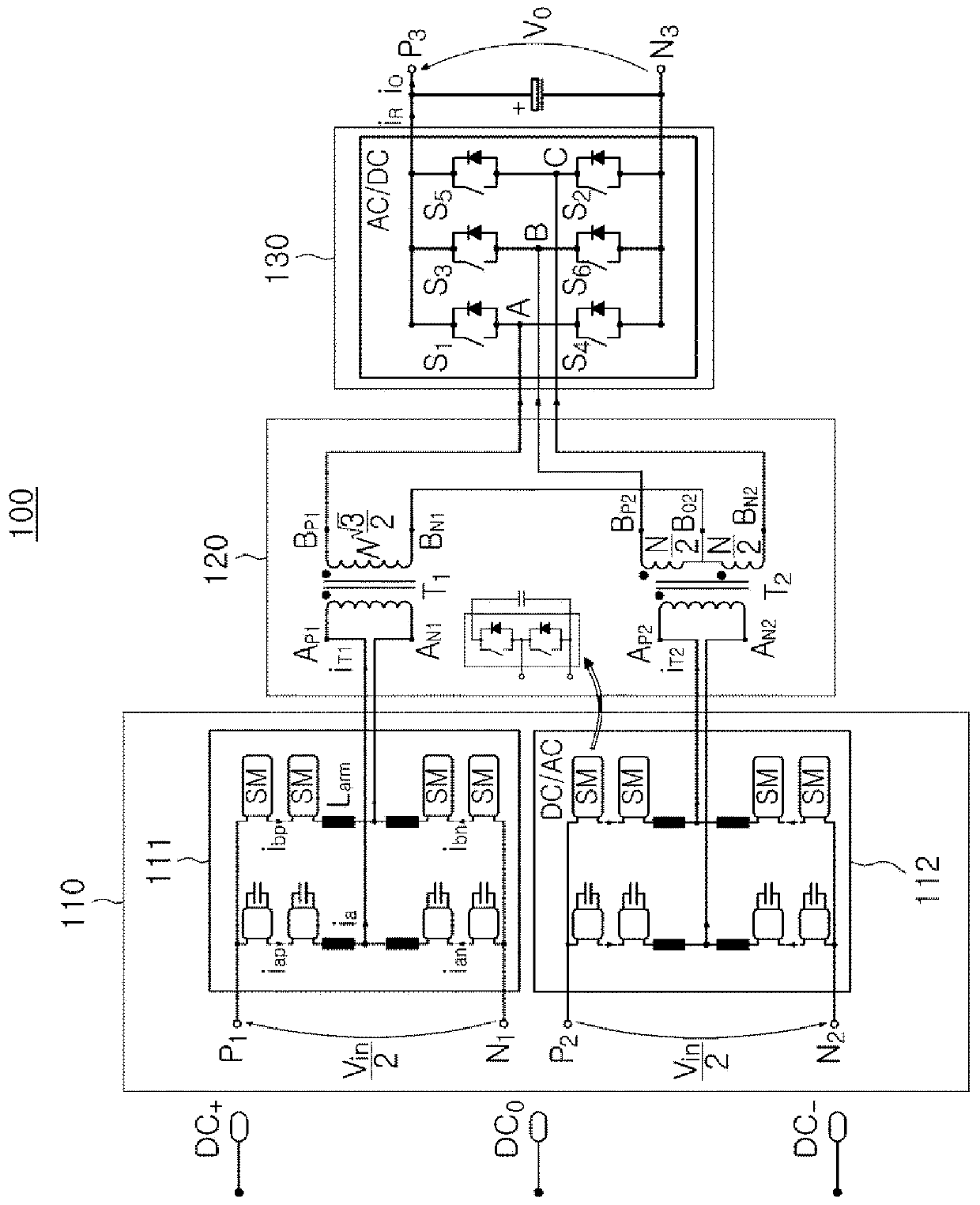
[0023] figure 1 is a schematic configuration diagram showing a power converter according to example embodiments.

[0024] refer to figure 1 , the power converter 100 according to example embodiments may include a direct current (DC) to alternating current (AC) converter 110 , a Scott-T transformer 120 and an alternating current (AC) to direct current (DC) converter 130 .

[0025] The DC to AC converter 110 may include at least two multilevel converters 111 and 112 .

[0026] Each of the at least two multilevel converters 111 and 112 may convert input direct current (DC) power into alternating current (AC) power. The multilevel converters 111 and 112 may be modular multilevel converters.

[0027] Each of the multilevel converters 111 and 112 may include first DC terminals P1 and N1 and second DC ...


PUM


Abstract

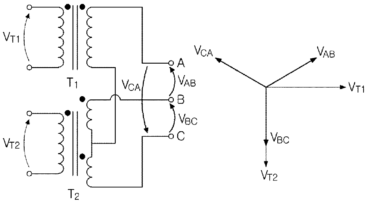
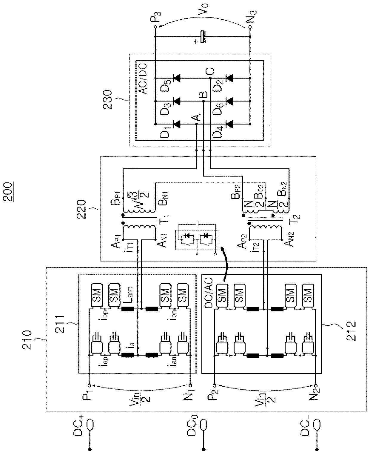
The present invention may comprise: a direct current-to-alternating current conversion unit having at least two multi-level converters each converting input direct-current power into alternating-current power; a Scott transformer which operates at a medium frequency of hundreds of Hz to tens of thousands of Hz so that a voltage level of the alternating-current power from each of the at least two multi-level converters of the direct current-to-alternating current conversion unit is transformed into three-phase alternating-current power to be output; and an alternating current-to-direct currentconversion unit for converting the three-phase alternating-current power from the Scott transformer into direct-current power.

Description


Claims


Application Information

Patent Timeline
Owner HYUNDAI ELECTRIC & ENERGY SYST CO LTD
Learn More