
Equipment suitable for testing performance of air valve of railway vehicle air conditioning unit

A technology for air-conditioning units and testing equipment, which is applied in the direction of mechanical valve testing, measuring electricity, and measuring devices. It can solve the problems of inconvenient disassembly and assembly, repeated disassembly and installation of damper tests, and inconvenient adjustment of parameters. The effect of improving maintenance efficiency and performance requirements

Pending Publication Date: 2020-04-24
优立科轨道交通技术有限公司
View PDF0 Cites 0 Cited by
  • Summary
  • Abstract
  • Description
  • Claims
  • Application Information

AI Technical Summary

Problems solved by technology

[0004] Inconvenient disassembly and assembly, because the internal layout of the air conditioning unit is compact, it is inconvenient to repeatedly disassemble and install the damper test;
[0005] The time is uncontrollable, because the driving of the air valve is carried out by the air valve actuator, the control of the air valve actuator needs to be set during the test, but most of the air conditioning units use PLC or embedded control, and it is inconvenient to adjust the parameters
[0006] There is currently no air valve test device specifically for rail vehicle air conditioning units on the market

Method used


Image

  • Equipment suitable for testing performance of air valve of railway vehicle air conditioning unit
  • Equipment suitable for testing performance of air valve of railway vehicle air conditioning unit
  • Equipment suitable for testing performance of air valve of railway vehicle air conditioning unit

Examples


Embodiment Construction

[0020] Embodiments of the present invention will be further described below with reference to the accompanying drawings:

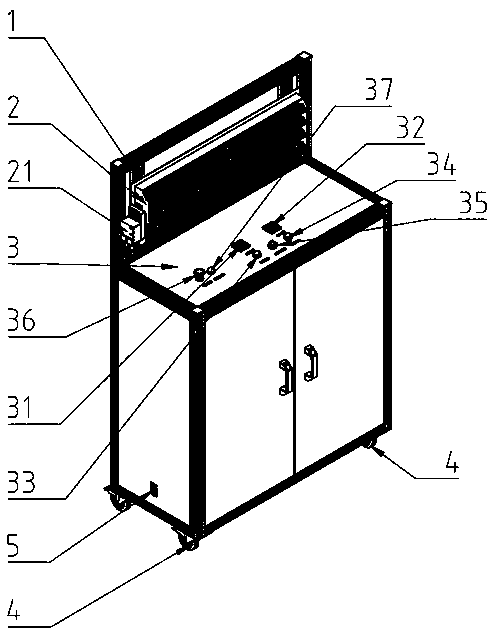
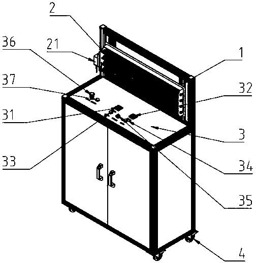
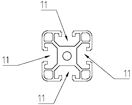
[0021] Such as Figure 1-Figure 3 As shown, the present embodiment provides a kind of test equipment suitable for the air valve performance of rail vehicle air-conditioning units, including a test bracket 1 and an operating platform 3, and the testing bracket 1 is installed on the side above the operating platform 3, and the testing bracket 1 is used to install the air valve 2, and the operation platform 3 is equipped with a forward rotation timer 31, a reverse rotation timer 32, a forward rotation switch 33 and a reverse rotation switch 34, and the forward rotation timer 31 and the forward rotation switch 33 Electrically connected to control its power-on time, the reverse timer 32 is electrically connected to the reverse switch 34 to control its power-on time, the air valve actuator 21 on the air valve 2 is electrically connected to a forward and reverse ...


PUM


Abstract

The invention belongs to the technical field of air valve testing and particularly relates to equipment suitable for testing the performance of an air valve of a railway vehicle air conditioning unit.The equipment comprises a test support and an operation platform. The test support is installed on one side of an upper portion of the operation platform. The test support is used for installing theair valve. A forward timer, a reverse timer, a forward switch and a reverse switch are mounted on the operating platform; the forward timer is electrically connected with the forward switch to controlthe power-on time of the forward switch; the reverse timer is electrically connected with the reverse switch to control the power-on time of the reverse switch; an air valve actuator on the air valveis electrically connected with a forward and reverse rotation mode, the forward and reverse rotation mode is electrically connected with the forward rotation switch and the reverse rotation switch toachieve the effect of mutually switching power-on modes, and the forward rotation switch and the reverse rotation switch are electrically connected with a power source to supply power. The problem that the air valve of the railway vehicle air conditioning unit is difficult to test is solved.

Description

technical field [0001] The invention belongs to the technical field of air valve testing, in particular to a test device suitable for the air valve performance of an air-conditioning unit of a rail vehicle. Background technique [0002] At present, the air valve test of rail vehicle air-conditioning units needs to be carried out inside the air-conditioning unit, but the defects of this method of testing are as follows: [0003] Occupies space, the test needs to be carried out on the air conditioning unit and the original unit must be in good working condition, otherwise there are many influencing factors; [0004] Inconvenient disassembly and assembly, because the internal layout of the air conditioning unit is compact, it is inconvenient to repeatedly disassemble and install the damper test; [0005] The time is uncontrollable, because the damper is driven by the damper actuator, the control of the damper actuator needs to be set during the test, but most air-conditioning ...

Claims


Application Information

Patent Timeline
IPC IPC(8): G01M13/003G01R31/00
CPCG01M13/003G01R31/00
Inventor 王洋
Owner 优立科轨道交通技术有限公司
Learn More