
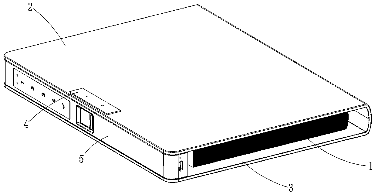
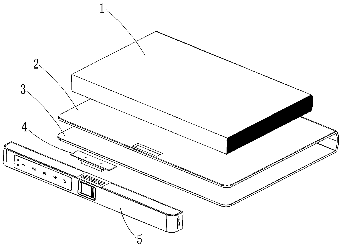
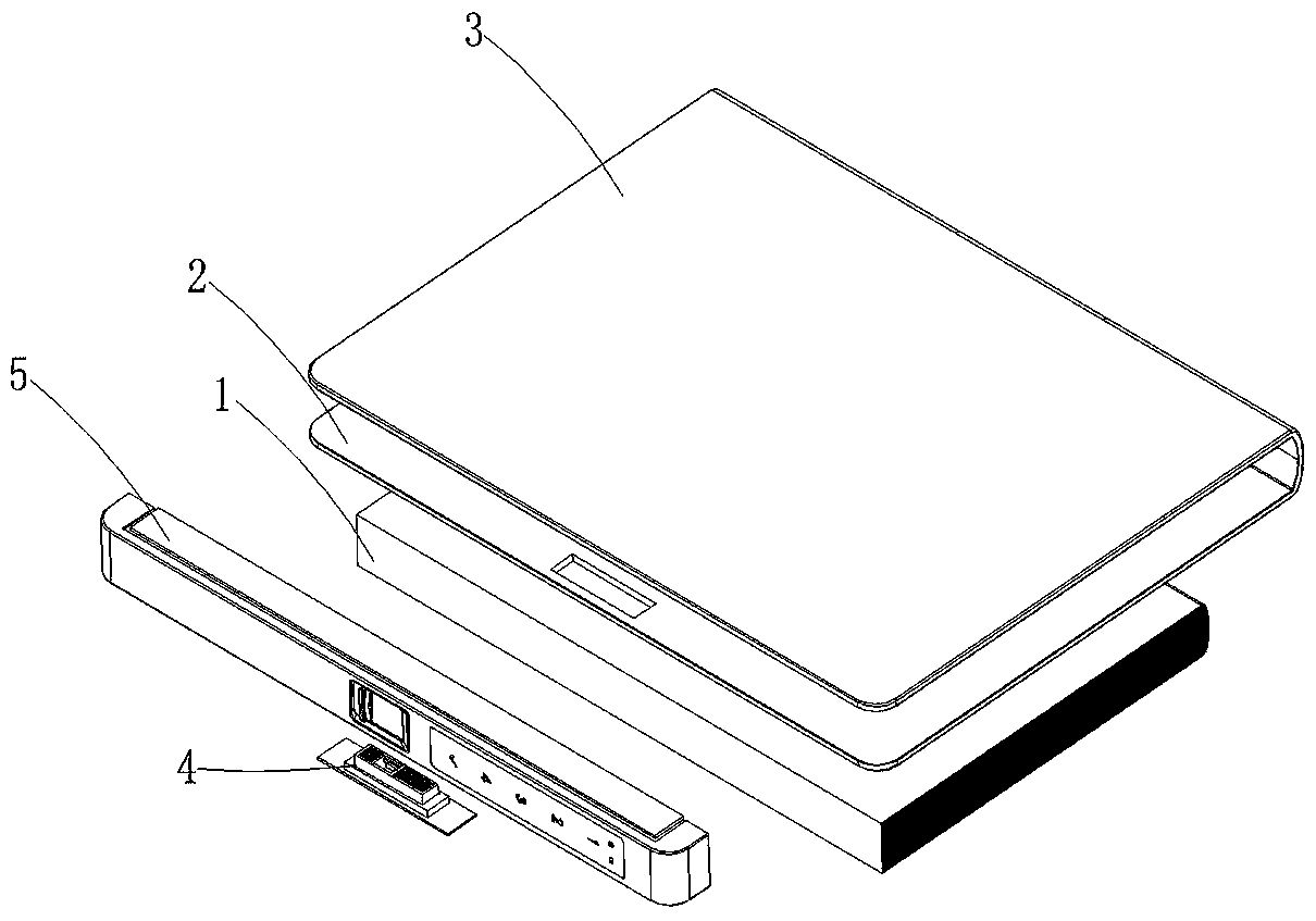
Lock body structure and notebook

A lock body and lock core technology, which is applied in bookkeeping, building locks, lock applications, etc., can solve the problems of time-consuming and labor-intensive operation, the lock body structure is not locked, and the notebook is easy to open, etc., so as to achieve convenient and fast operation and prevent The effect of leaking secrets and improving security and confidentiality capabilities

Pending Publication Date: 2020-05-01
NINGBO WANGTONG LOCKS
View PDF0 Cites 1 Cited by
  • Summary
  • Abstract
  • Description
  • Claims
  • Application Information

AI Technical Summary

Problems solved by technology

Most notebooks do not have any snap-close structure, so the notebook is easy to open during carrying, resulting in the leakage of secrets
In order to achieve the purpose of confidentiality, some existing notebooks will be equipped with more traditional finger-type mechanical combination locks, but this type of lock is relatively simple, easy to be cracked, and the operation is time-consuming and laborious
In addition, there are also some fingerprint locks that have been used in notebooks, but they have locking defects. This defect is divided into two situations. The first is that after unlocking and opening the notebook, the fingerprint lock automatically re-locks after a certain period of time. When closing the notebook, it is necessary to re-unlock the fingerprint lock and quickly lock the lock body structure during the automatic locking period; the second is to unlock and open the notebook. After the lock body structure is not locked, it is necessary to re-lock the lock body structure through the fingerprint lock operation

Method used


Image

  • Lock body structure and notebook
  • Lock body structure and notebook
  • Lock body structure and notebook

Examples


Embodiment Construction

[0035] The present invention will be described in further detail below in conjunction with the accompanying drawings and specific embodiments.

[0036] refer to Figure 1 to Figure 13 , a lock body structure, including a lock box assembly 4 and a lock cylinder main body 5;

[0037] The lock box assembly 4 includes a box body 401 and an adaptive locking assembly, the box body 401 is provided with an inner cavity 402, and the box body 401 is provided with a through groove 403 communicating with the inner cavity 402, so The self-adaptive locking component is arranged in the inner cavity 402 and is located on one side of the through groove 403, and the above-mentioned adaptive locking component and the through groove 403 partially overlap in the upper and lower positions, that is, when locking, it can allow The locking tongue 503 moves upward through the overlapping portion, and makes the self-adaptive locking component interfere with the locking tongue 503 to form a locking effe...


PUM


Abstract

The invention discloses a lock body structure and a notebook. The notebook comprises an envelope and a papery inner core. The envelope comprises an upper cover and a lower cover. The notebook furthercomprises the following lock body structure. The lock body structure comprises a lock case assembly and a lock cylinder body. The lock case assembly comprises a case body and a self-adaptive locking assembly. An inner cavity is formed in the case body. A through groove communicating with the inner cavity is formed in the case body. The self-adaptive locking assembly is arranged in the inner cavityand located on the side where the through groove is located. The lock cylinder body comprises a lock cylinder shell, a push block arranged in the lock cylinder shell, an electronic lock assembly anda push button unlocking assembly. A spring bolt capable of being inserted into the through groove is arranged on the push block. The push button unlocking assembly is in transmission connection with the push block. An elastic reset part is arranged between the push block and the lock cylinder shell. According to the lock body structure and the notebook, a traditional lock body structure of a mechanical structure and a traditional electronic lock structure are combined and applied into the notebook, the automatic locking function is achieved, the security and secrecy capacity of the notebook isgreatly improved, and the unlocking speed is also greatly increased.

Description

technical field [0001] The invention belongs to the technical field of lock structure and application, in particular to a lock body structure and a notebook. Background technique [0002] Office notebooks currently on the market include an upper cover, a plurality of note pages and a lower cover. The plurality of note pages are all arranged between the upper cover and the lower cover. One side of the upper cover and the lower cover One side is connected with one side of a plurality of note pages. In existing notebooks, the upper and lower covers are generally only connected by clamping and closing structures such as inserts or buttons. [0003] Some people like to clip business cards, invoices and other receipts in their notebooks. Because small items such as business cards and receipts are small in size and light in weight, they are easy to drop or even lose during carrying. In addition, some records in the notebook will involve important secrets or personal privacy and n...

Claims


Application Information

Patent Timeline
Patent Type & Authority Applications(China)
IPC IPC(8): E05B47/00E05B17/20E05B49/00G07C9/00B42D3/10B42D12/00
CPCE05B47/0012E05B47/0607E05B17/2019E05B49/00G07C9/00563B42D3/10B42D12/00E05B2047/0058E05B2047/0036
Inventor 韩文杰王壤
Owner NINGBO WANGTONG LOCKS
Learn More