
Antenna adjustment method and device

An adjustment method and antenna technology, applied to antennas, antenna arrays, antenna combinations with different interactions, etc., can solve the problems of fixed antenna radiation performance and the inability to guarantee good antenna performance, and achieve good performance results

Active Publication Date: 2022-02-18
SHENZHEN ANTOP TECH
View PDF5 Cites 0 Cited by
  • Summary
  • Abstract
  • Description
  • Claims
  • Application Information

AI Technical Summary

Problems solved by technology

[0004] The embodiment of the present application provides an antenna adjustment method and device, which can solve the problem that the radiation performance of the current antenna is fixed, and it is impossible to ensure that the antenna performs well in the face of different frequency requirements of electronic equipment.

Method used


Image

  • Antenna adjustment method and device
  • Antenna adjustment method and device
  • Antenna adjustment method and device

Examples


Embodiment Construction

[0027] In the following description, specific details such as specific system structures and techniques are proposed for explanation, such as specific details, such as specific system structures, and techniques. However, it will be apparent to those skilled in the art that the present application can also be implemented in other embodiments without these specific details. In other cases, a detailed description of well known systems, devices, circuits, and methods is omitted to prevent unnecessary details to prevent the presentation.

[0028] The antenna adjustment method provided herein can be applied to an antenna device such as a communication antenna, a broadcast antenna, a television antenna, and the specific type of the antenna device is not limited.

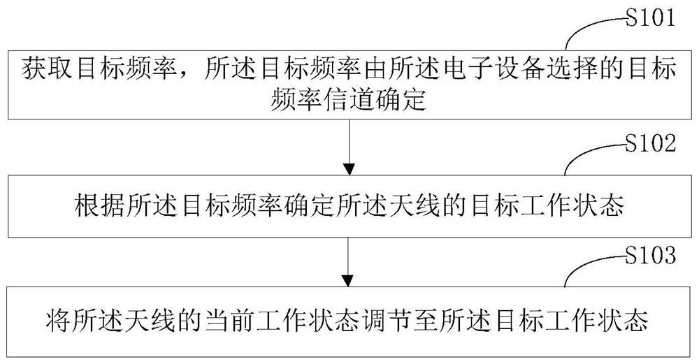
[0029] figure 1 The implementation flow chart of the antenna adjustment method provided in Example 1 of the present invention is shown, and detailed is as follows:

[0030] An antenna adjustment method is applied to an antenna...


PUM


Abstract

This application is applicable to the field of antenna technology, and provides an antenna adjustment method and device. By obtaining the frequency channel sent by the TV equipment, the current working frequency and the corresponding target working state of the TV antenna are determined, and the current working frequency of the antenna is adjusted. state to the target working state, so as to adjust the radiation performance of the antenna, so that the antenna performs well when facing different frequency requirements of electronic equipment.

Description

Technical field [0001] The present application belongs to the field of antenna, in particular, to antenna adjustment method and device. Background technique [0002] At present, when the electronic device replaces the playback frequency channel, the antenna receives the frequency channel information (digital signal code stream) transmitted by the television, decodes the information of the TV frequency channel, resulting in the operating frequency of the antenna, and receiving at this operating frequency Electromagnetic wave signal. However, most of the antennas on the market are fixed, and the impedance, radiation direction, gain, etc. of the antenna are unchanged during use. Therefore, in the case where the radiation performance of the antenna is fixed, it is not easy to control if the electromagnetic wave signal is good when the electromagnetic wave signal is improved in the face of different frequency requirements of the electronic device. [0003] In summary, the radiation pe...

Claims


Application Information

Patent Timeline
Patent Type & Authority Patents(China)
IPC IPC(8): H01Q1/36H01Q3/00H01Q21/29H04N21/438
CPCH01Q3/00H01Q1/36H01Q21/29H01Q21/293H04N21/4383
Inventor 杨瑞典孔爱华陆伟明
Owner SHENZHEN ANTOP TECH
Learn More