Sweeping robot working face cleaning method

A sweeping robot and working surface technology, applied in robot cleaners, manual sweeping machines, cleaning machines, etc., can solve the problems of low cleaning efficiency of sweeping robots, improve visual cleanliness, improve cleaning efficiency, and reduce idling and idling Effect

Active Publication Date: 2020-05-08
XIAOGOU ELECTRIC INTERNET TECH BEIJING CO LTD
View PDF6 Cites 5 Cited by
  • Summary
  • Abstract
  • Description
  • Claims
  • Application Information

AI Technical Summary

Problems solved by technology

[0003] In view of the above analysis, the present invention aims to provide a cleaning method for the working

Method used


Image

  • Sweeping robot working face cleaning method
  • Sweeping robot working face cleaning method
  • Sweeping robot working face cleaning method

Examples


Embodiment 1

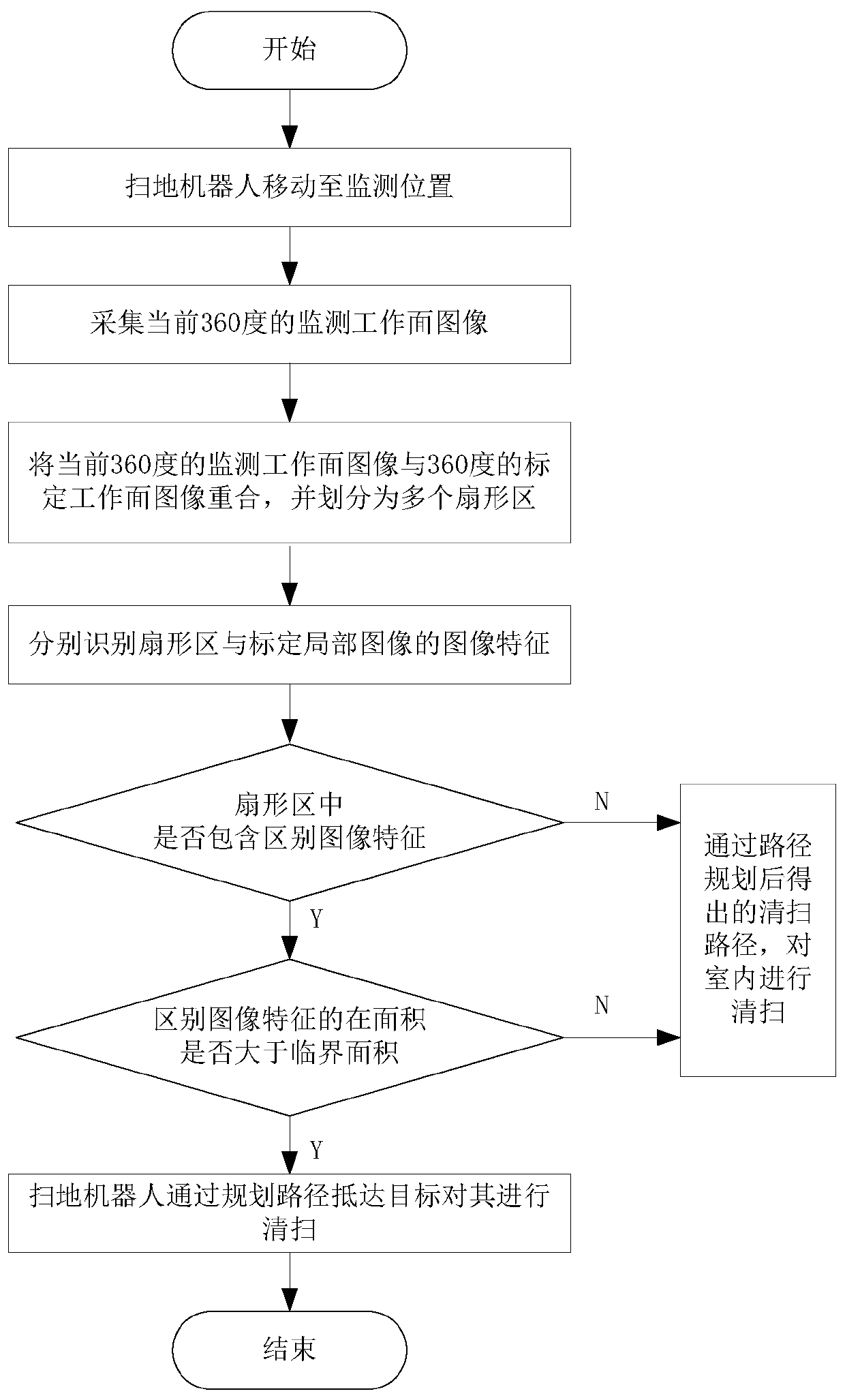
[0060] Such as figure 1 Shown:

[0061] S1. Move the sweeping robot to the monitoring position according to the guidance of the working surface space map;

[0062] S2. Take a 360° monitoring work surface image centered on the monitoring position by the sweeping robot;

[0063] When the sweeping robot reaches the monitoring position, keep the sweeping robot stationary, rotate the image acquisition device of the LDS component on the sweeping robot, and shoot a 360° monitoring work surface image with the monitoring position as the center, that is, keep the sweeping robot still while rotating image collection Equipment; superimpose the captured image of the monitoring work surface with the calibration image of the monitoring location, and divide it into multiple fan-shaped areas at equal rotation angles to improve the accuracy of the comparison between the captured image of the monitoring work surface and the calibration image of the monitoring location.

[0064] S3. Compare the captured ...

Embodiment 2

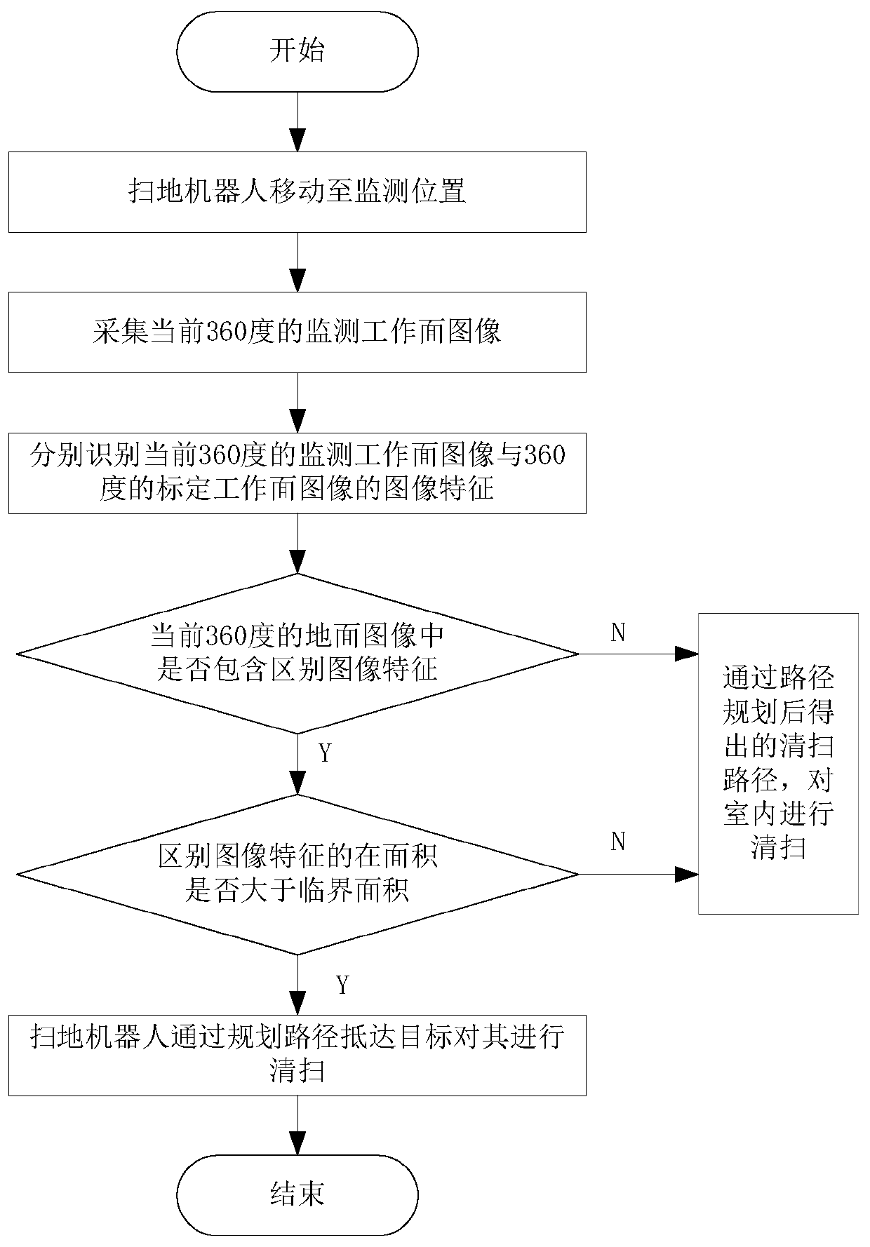
[0070] Such as figure 2 Shown:

[0071] S1. Move the sweeping robot to the monitoring position according to the guidance of the working surface space map;

[0072] S2. Take a 360° monitoring work surface image centered on the monitoring position by the sweeping robot;

[0073] When the sweeping robot reaches the monitoring position, keep the sweeping robot and the image acquisition device of the LDS component on the sweeping robot relatively stationary, rotate the sweeping robot, and take a 360° monitoring work surface image with the monitoring position as the center, that is, keep the image collection Rotate the sweeping robot without moving the device. The overall comparison can increase the speed of the comparison between the captured image of the monitoring work surface and the calibration image of the monitoring position.

[0074] S3. Compare the captured image of the monitoring work surface with the calibration image of the monitoring position, and obtain the distinguishing i...


PUM


Abstract

The invention relates to a sweeping robot working face cleaning method, belongs to the field of automatic cleaning equipment, and solves the problem that an existing sweeping robot is low in cleaningefficiency. The cleaning method comprises the following steps: moving the sweeping robot to a monitoring position under the guidance of a working surface space diagram; a 360-degree monitoring workingface image with the monitoring position as the center is shot through the sweeping robot; comparing the shot monitoring working surface image with the calibration image of the monitoring position, obtaining a distinguishing image feature in the image, If the area of the working surface corresponding to the distinguishing image feature is greater than the critical area, determining that the distinguishing image feature is a target feature; determining the corresponding target position of the target feature on the working face space diagram through the shot monitored working face image; and thesweeping robot is moved to the target position to clean the working face. By means of the method, large-area foreign matter can be removed preferentially, the overall cleanness of the ground is guaranteed, and the cleaning efficiency is improved.

Description

Technical field [0001] The invention relates to the technical field of automatic cleaning equipment, in particular to a method for cleaning the working surface of a sweeping robot. Background technique [0002] The sweeping robot cleans the room, generally according to the bow-shaped path or the tic-shaped path planned by the indoor map, and cleans the dust particles on the ground during the traveling process. However, if there is a large area of ​​particles on the ground, the sweeping robot cannot immediately reach the position of the particles to clean it, resulting in a messy ground. In addition, the sweeping robot keeps cruising indoors, which will cause Long-term idling causes energy waste and low cleaning efficiency. Summary of the invention [0003] In view of the above analysis, the present invention aims to provide a cleaning method for the working surface of a sweeping robot to solve the problem of low cleaning efficiency of the existing sweeping robot. [0004] The purp...

Claims


Application Information

Patent Timeline
IPC IPC(8): A47L11/24A47L11/40
CPCA47L11/24A47L11/4005A47L11/4008A47L2201/00A47L2201/02A47L2201/06
Inventor 檀冲严涛
Owner XIAOGOU ELECTRIC INTERNET TECH BEIJING CO LTD
Why Eureka
Try Eureka