A radiator water separator manufacturing device

A technology for manufacturing devices and water separators, which is applied in the field of pipe fittings processing, can solve problems such as high cost, unqualified mold shrinkage, and unsuitability for small and medium-sized enterprises, and achieve the effect of improving efficiency and ensuring quality

Active Publication Date: 2021-07-27
保定圣通散热器制造有限公司
View PDF0 Cites 0 Cited by
  • Summary
  • Abstract
  • Description
  • Claims
  • Application Information

AI Technical Summary

Problems solved by technology

my country's industrial policy on the development of civil radiators has been clear: In the next ten years or so, light radiators mainly made of steel will gradually replace traditional cast iron radiators; there is an important part inside the steel plate radiator. Water dispenser, which plays the role of water separation, conduction and support. Its structure is to squeeze the edges of the two ends of the rough pipe inward to make it flanging. The flanging after extrusion is flush with the horizontal surface. The finished product of the water separator is finally obtained by drilling. At present, for large enterprises, the production of the water separator is formed at one time with a special mold, but the cost of using the special mold is too high, and it is not suitable for the production of small and medium-sized enterprises. At present, there is no suitable for small and medium-sized enterprises Mass production of radiator water divider devices, and the finished products produced by the water divider devices designed by many small and medium-sized enterprises are unqualified and cannot be directly used in radiators. Therefore, it is necessary to design a device suitable for mass production of small and medium-sized enterprises. The device of water divider, to solve the problem that prior art exists

Method used


Image

  • A radiator water separator manufacturing device
  • A radiator water separator manufacturing device
  • A radiator water separator manufacturing device

Examples


Embodiment Construction

[0035] The following will clearly and completely describe the technical solutions in the embodiments of the present invention with reference to the accompanying drawings in the embodiments of the present invention. Obviously, the described embodiments are only some, not all, embodiments of the present invention. Based on the embodiments of the present invention, all other embodiments obtained by persons of ordinary skill in the art without making creative efforts belong to the protection scope of the present invention.

[0036]In order to make the above objects, features and advantages of the present invention more comprehensible, the present invention will be further described in detail below in conjunction with the accompanying drawings and specific embodiments.

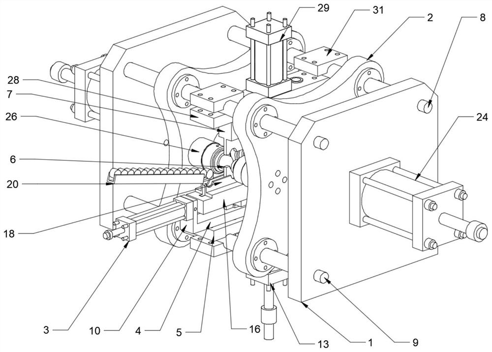
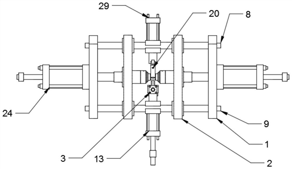
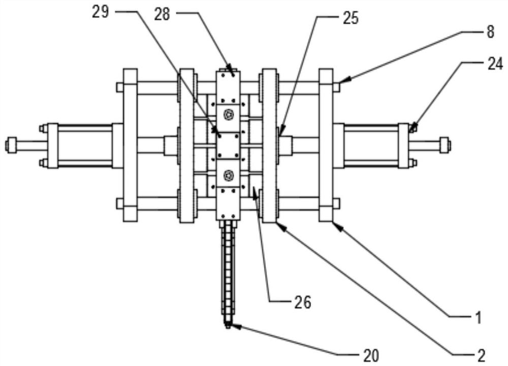
[0037] refer to Figure 1-13 , The invention provides a radiator water separator manufacturing device, including a support mechanism, an extrusion mechanism, an automatic feeding mechanism and a positioning mechani...


PUM


Abstract

The invention provides a radiator water distributor manufacturing device, which includes a support mechanism, an extrusion mechanism, an automatic feeding mechanism and a positioning mechanism; the support mechanism includes a fixed plate, a push plate and a sliding rod group; the extrusion mechanism includes an extrusion cylinder assembly, Two extrusion column groups and two mold cavity groups; the automatic feeding mechanism includes a feeding mechanism, a horizontal feeding cylinder, a first support beam, a lower cylinder assembly, a second support beam and a feeding table; the positioning mechanism includes a lower positioning plate, an upper The positioning plate and the upper oil cylinder assembly; the supporting mechanism supports the extrusion mechanism, the automatic feeding mechanism and the positioning mechanism, the automatic feeding mechanism sends the blank to the positioning mechanism, and the extrusion mechanism squeezes and shapes the blank in the positioning mechanism. The manufacturing device of the radiator water separator of the present invention enables the blank tube to be sequentially extruded through four mold cavities, and finally the blank tube is compression-molded into a qualified finished product, has a simple structure and low cost, and is suitable for mass production of small and medium-sized enterprises.

Description

technical field [0001] The invention relates to the technical field of pipe fitting processing, in particular to a radiator water separator manufacturing device. Background technique [0002] Pipe necking is a forming process that reduces the diameter of the end of the tube blank. The tube blank enters the deformation zone under the action of axial force, and produces tangential shrinkage plastic deformation in the deformation zone, and then enters the stable zone, and finally forms a reduced end. internal diameter. In addition, as the main representative of light-weight radiators, steel radiators are deeply loved by consumers because of their easy-to-obtain materials, high thermal efficiency, energy saving, material saving, beautiful appearance and environmental protection. my country's industrial policy on the development of civil radiators has been clear: In the next ten years or so, light radiators mainly made of steel will gradually replace traditional cast iron radiat...

Claims


Application Information

Patent Timeline
Patent Type & Authority Patents(China)
IPC IPC(8): B21D53/06B21D41/04B21D43/00B21D43/02
CPCB21D41/04B21D43/003B21D43/02B21D53/06
Inventor 王景中
Owner 保定圣通散热器制造有限公司
Why Eureka
Try Eureka