
Crane main beam connecting rod lifting device

A lifting device and crane technology, applied in the direction of the lifting device, etc., can solve the problems of difficult processing of connecting rods and poor use effect, and achieve the effect of convenient processing and manufacturing and reducing processing difficulty.

Inactive Publication Date: 2020-05-08
HENAN MINE CRANE
View PDF7 Cites 6 Cited by
  • Summary
  • Abstract
  • Description
  • Claims
  • Application Information

AI Technical Summary

Problems solved by technology

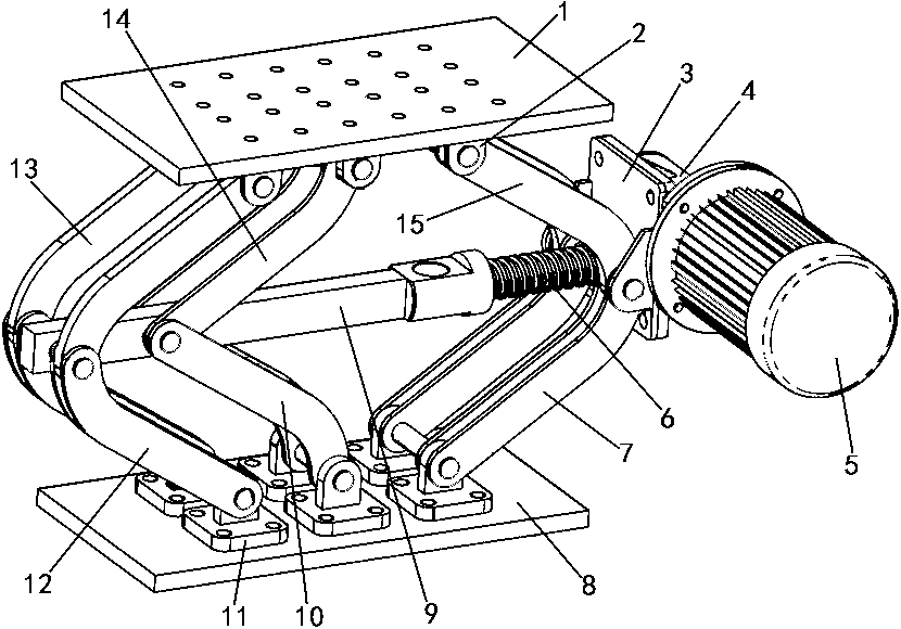
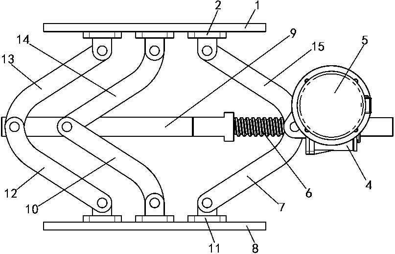
[0004] The object of the present invention is to provide a lifting device for the connecting rod of the main girder of a crane, so as to solve the problems that the connecting rod of the connecting rod lifting device in the prior art is difficult to process and the use effect is poor

Method used


Image

  • Crane main beam connecting rod lifting device
  • Crane main beam connecting rod lifting device
  • Crane main beam connecting rod lifting device

Examples


Embodiment Construction

[0033] In order to make the objectives, technical solutions and advantages of the present invention clearer, the following further describes the present invention in detail with reference to the accompanying drawings and embodiments. It should be understood that the specific embodiments described herein are only used to explain the present invention and not to limit the present invention, that is, the described embodiments are only a part of the embodiments of the present invention, rather than all the embodiments. The components of the embodiments of the present invention generally described and illustrated in the drawings herein may be arranged and designed in various different configurations.

[0034] Therefore, the following detailed description of the embodiments of the present invention provided in the accompanying drawings is not intended to limit the scope of the claimed invention, but merely represents selected embodiments of the present invention. Based on the embodimen...


PUM


Abstract

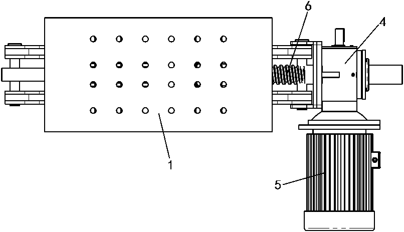
The invention provides a crane main beam connecting rod lifting device. The crane main beam connecting rod lifting device comprises a base, a bracket, a lead screw, a power driving mechanism, a firstupper connecting rod, a first lower connecting rod, a second upper connecting rod, a second lower connecting rod, a third upper connecting rod and a third lower connecting rod. The bottom end of the first upper connecting rod is hinged to the top end of the first lower connecting rod, and the lead screw straightly moves left and right under the action of the power driving mechanism. The bottom endof the second upper connecting rod and the top end of the second lower connecting rod are hinged to the lead screw at the same time, and the bottom end of the third upper connecting rod and the top end of the third lower connecting rod are hinged to the lead screw at the same time. A parallelogram mechanism is formed by the base, the second lower connecting rod, the third lower connecting rod andthe lead screw, and a parallelogram mechanism is formed by the bracket, the second upper connecting rod, the third upper connecting rod and the lead screw. The crane main beam connecting rod liftingmechanism has the advantages that the connecting rods are hinged, the connecting rods and the other components are hinged, tooth structure do not need to be machined on the connecting rods, and machining and manufacturing are convenient; and meanwhile the problem that the tooth structures are adopted for keeping the synchronization action of the connecting rods, and consequently the use effect ispoor is avoided.

Description

Technical field [0001] The invention relates to a crane main beam connecting rod lifting device. Background technique [0002] The jack is a well-known lifting device, especially the electric scissor jack. It uses a rigid lifting piece as a working device. It lifts heavy objects within the stroke through the top pallet and the bottom base. Heavy equipment. For example, a four-link electric jack (that is, a connecting rod lifting device) disclosed in the Chinese utility model patent with the authorized announcement number CN202107479U includes a bracket, an upper connecting rod, a lower connecting rod, a base, a screw rod, and a pin The column nut, the geared motor, and the upper and lower connecting rods form a four-link mechanism. One end is hinged on the bracket and the other end is hinged on the base; the upper and lower connecting rods on the right are spliced ​​with pin nuts. There is a geared motor at the joint of the upper and lower connecting rods on the left; one end o...

Claims


Application Information

Patent Timeline
Patent Type & Authority Applications(China)
IPC IPC(8): B66F3/12B66F3/44
CPCB66F3/12B66F3/44
Inventor 邵东亮马文波丰树礼黄晓琳姬宏赟郑沛陈刚胡胜超申强
Owner HENAN MINE CRANE
Learn More