Multi-angle reversing device for door lock handle

A reversing device, multi-angle technology, applied in the direction of handle connection, building lock, lock shell, etc., can solve different installation scenarios, the connecting rod is easy to fall up or down, inconvenient door lock packaging and transportation, etc. problems, to achieve the effect of convenient packaging and transportation, reducing installation costs, and simple structure

Active Publication Date: 2018-10-16
浙江超虎智能科技有限公司
View PDF3 Cites 4 Cited by
  • Summary
  • Abstract
  • Description
  • Claims
  • Application Information

AI Technical Summary

Problems solved by technology

[0002] The traditional door lock handle can only be installed to the left or right, and the installation direction is single. In order to facilitate transportation, the handle and the lock surface are usually separated, and then installed on site. Not only the installation direction needs to be distinguished during installation, but also the installation process is prone to problems. Parts are scattered, the installation structure is not stable enough, the installation process is complicated, the installation efficiency is low, and it cannot be applied to different installation scenarios
[0003] Moreover, the anti-lock button of a traditional door lock can usually rotate 360°, which brings certain difficulties to the installation of the door lock. When installing, you must hold the connecting rod to insert it into the lock cylinder. Small, the connecting rod is easy to fall upwards or downwards, which takes a long time and reduces the installation efficiency. However, if the connecting rod is fixed and connected vertically with the lock surface, it will affect the packaging of the door lock, which is not convenient for the packaging of the door lock and transport

Method used


Image

  • Multi-angle reversing device for door lock handle
  • Multi-angle reversing device for door lock handle
  • Multi-angle reversing device for door lock handle

Examples


Embodiment Construction

[0032] In order to enable those skilled in the art to better understand the solutions of the present invention, the technical solutions in the embodiments of the invention will be clearly and completely described below in conjunction with the drawings in the embodiments of the present invention. Obviously, the described embodiments are only It is a part of embodiments of the present invention, but not all embodiments. Based on the embodiments of the present invention, all other embodiments obtained by persons of ordinary skill in the art without making creative efforts shall fall within the protection scope of the present invention.

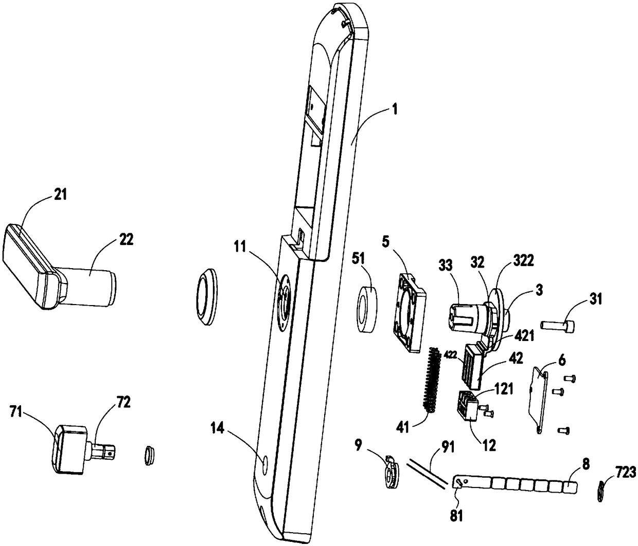
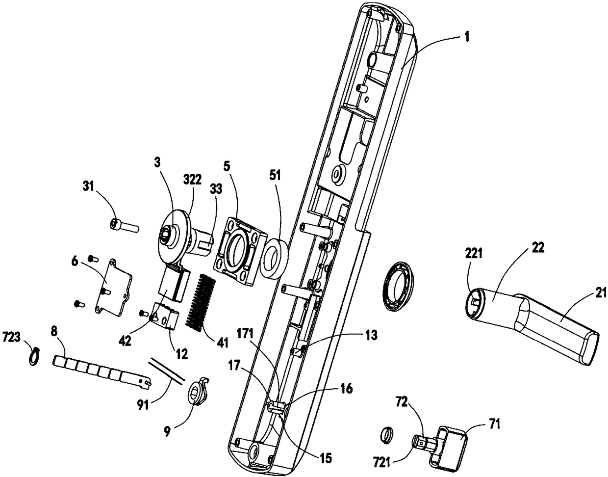
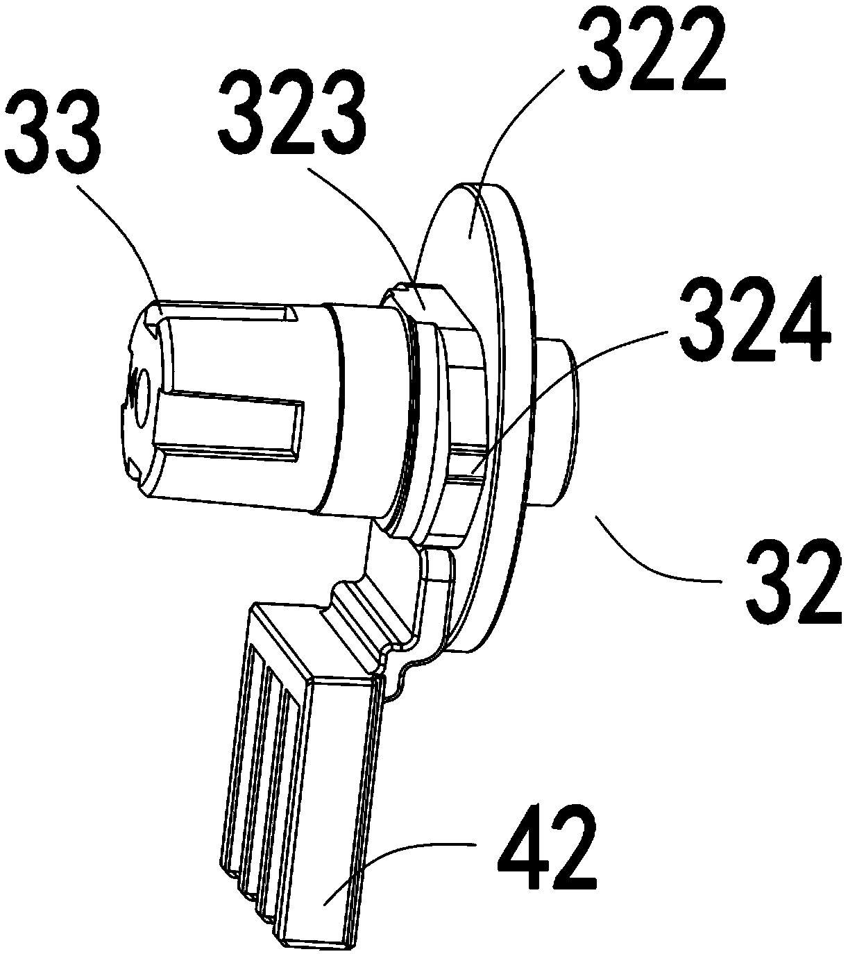
[0033] Such as Figure 1-14 As shown, a multi-angle reversing device for a door lock handle includes a lock face 1 and a handle 21, a lock hole 11 is opened on the lock face 1, and a connecting section 22 fixedly connected with the handle 21 passes through the lock hole 11 and the rotating member 3 Anti-rotation fit, specifically, the inner wall...


PUM


Abstract

The invention discloses a multi-angle reversing device for a door lock handle. The device comprises a lock surface, a handle rotatably connected to the lock surface through a connecting section, an elastic assembly and a counter lock rotary knob transmission device, wherein the counter lock rotary knob transmission device is connected to a lock cylinder through a connecting rod; the counter lock rotary knob transmission device comprises a rotary knob part and an extended section body, and a connecting seat is arranged on the extended section body in a sleeving manner; a notch part is formed inthe end part of the extended section body, and an anti-inverted supporting leg is formed on the connecting rod; the connecting section penetrating a lock hole in the lock surface is in rotation-stopping fit to a rotary part, and the lock hole is formed in a counter lock hole; a rotation-stopping bump is formed on the rotary part, and at least two rotation-stopping surfaces are formed on the rotation-stopping bump; a transitional surface is formed between adjacent rotation-stopping surfaces; and the elastic assembly comprises an elastic part, a movable substrate pushed by the elastic part to move up and down and an extended section arranged on the movable substrate to be in contact fit to the rotation-stopping bump. The multi-angle reversing device disclosed by the invention is simple in structure, high in mounting efficiency, low in mounting cost and convenient to package and transport, and it is labor-saving to rotate the handle.

Description

technical field [0001] The invention belongs to the technical field of intelligent locks, in particular to a multi-angle reversing device for a door lock handle. Background technique [0002] The traditional door lock handle can only be installed to the left or right, and the installation direction is single. In order to facilitate transportation, the handle and the lock surface are usually separated, and then installed on site. Not only the installation direction needs to be distinguished during installation, but also the installation process is prone to problems. Parts are scattered, the installation structure is not stable enough, the installation process is complicated, the installation efficiency is low, and it cannot be applied to different installation scenarios. [0003] Moreover, the anti-lock button of a traditional door lock can usually rotate 360°, which brings certain difficulties to the installation of the door lock. When installing, you must hold the connectin...

Claims


Application Information

Patent Timeline
Patent Type & Authority Applications(China)
IPC IPC(8): E05B3/00E05B9/00E05B15/00E05B17/22
Inventor 翁斌李世富
Owner 浙江超虎智能科技有限公司
Why Eureka
Try Eureka