AI technical title is built by Patsnap AI team. It summarizes the technical point description of the patent document.
A key and button technology, applied in electrical components, electrical switches, circuits, etc., to solve problems such as abnormal noise
Pending Publication Date: 2021-05-11
GREE ELECTRIC APPLIANCES INC
View PDF0 Cites 0 Cited by
Summary
Abstract
Description
Claims
Application Information
AI Technical Summary
This helps you quickly interpret patents by identifying the three key elements:
Problems solved by technology
Method used
Benefits of technology
Problems solved by technology
[0003] Therefore, the technical problem to be solved by the present invention is to overcome the defect that the rotary motion of the key structure in the prior art is likely to cause abnormal noise, thereby providing a key structure that reduces the probability of abnormal noise and improves the smoothness of use.
[0004] Another technical problem to be solved by the present invention is to overcome the defect that the button structure on the handleassembly in the prior art adopts the form of rotary motion to easily cause abnormal noise, so as to provide a handle assembly that reduces the probability of abnormal noise and improves the smoothness of use
[0005] Another technical problem to be solved by the present invention is to overcome the defect that the button structure on the vacuum cleaner in the prior art adopts the form of rotating motion to easily cause abnormal noise, so as to provide a vacuum cleaner that reduces the probability of abnormal noise
Method used
Image
Click on the blue label to locate the original text in one second.
Reading with bidirectional positioning of images and text.
Examples
Embodiment 1
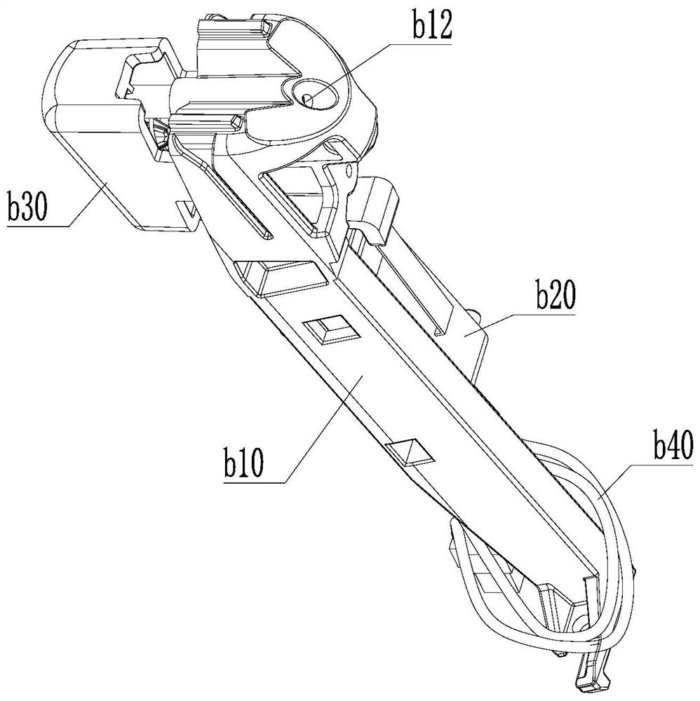
[0053] to combine Figure 1-Figure 8 As shown, the button structure provided by this embodiment includes:
[0054] Main body bracket b10;
[0055] a micro switch b20 installed on the main body bracket b10; and
[0056] The key body b30 is movably arranged on the main body bracket b10, and is suitable for turning on the micro switch b20 in a pressed state, and closing the micro switch b20 in a non-pressed state.
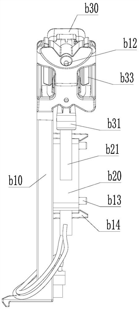
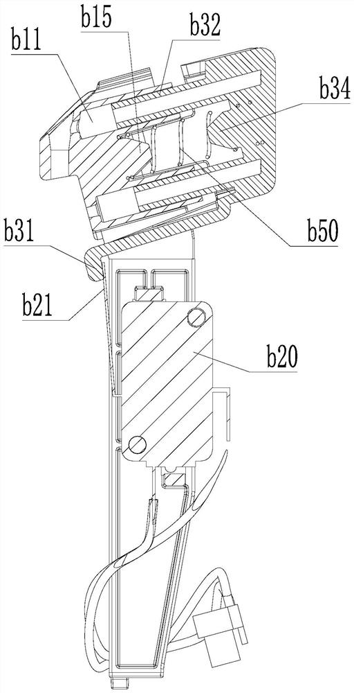
[0057] to combine Figure 7 , Figure 8 As shown, different from the traditional micro switch control form, the micro switch b20 provided in this embodiment is controlled by the key body b30. When the key body b30 is pressed, the elastic piece b21 of the micro switch b20 is far away from the micro switch. The main body, the shrapnel b21 loosens the pressure on the operation button b23, so that the moving reed b24 inside the micro switch contacts the normally closed contact b25; when the key body b30 is not pressed, the shrapnel b21 of the micro switch b20 is close...
Embodiment 2
[0095] This embodiment provides a handle assembly, including: the button structure as described above.
[0096] Preferably, the handle assembly is convenient for the user to hold, and at the same time, a button structure is provided on the handle assembly, which is convenient for the user to operate.
[0097] In the handle assembly provided in this embodiment, the button structure is arranged inside the handle assembly, and the button body b30 and the micro switch b20 are preferably arranged along the length direction of the handle assembly, so that the button body b30 opens the button in the pressed state. The micro switch b20, and closing the micro switch b20 in the non-pressed state, so that the micro switch b20 and the key body b30 can be reasonably arranged, so that the micro switch b20 and the key body b30 can be placed relative to each other along the up and down direction, There is no need to place it along the front and back directions, and it is convenient to arrange...
Embodiment 3
[0099] This embodiment provides a vacuum cleaner, including: the above-mentioned handle assembly.
PUM
Abstract
The invention relates to the technical field of key structures, in particular to a key structure, a handleassembly and a dust collector. The key structure comprises a main body support; a microswitch mounted on the main body support; and a key body which is movably arranged on the main body support and is suitable for turning on the microswitch in a pressed state and turning off the microswitch in a non-pressed state. According to the key structure provided by the invention, the microswitch and the key body can be reasonably arranged, so that the microswitch and the key body can be oppositely placed along the up-down direction and do not need to be placed along the front-back direction, the occupied space along the movement direction of the key body is greatly saved, and the space along the up-down direction of the key body is reasonably utilized; by changing the control mode and the layout mode, the space is saved, the control effect is ensured, and application in a working environment in which the space in the movement direction of the key body is relatively narrow is facilitated.
Description
technical field [0001] The invention relates to the technical field of button structures, in particular to a button structure, a handleassembly and a vacuum cleaner. Background technique [0002] The micro switch is a switch in which the external mechanical force acts on the action reed through the transmission element, so that the fixed contact at the end and the moving contact are quickly connected or disconnected. Usually, it can be activated with a very small force. In order to trigger the micro switch, a button structure is usually set to facilitate manual operation; however, in some structures with small installation space, due to the limited space, it is necessary to use a reasonable design to ensure that it can be installed firmly and the button can be adjusted to the micro switch. The trigger action of the switch is smooth. In addition, conventional buttons often adopt the form of rotary motion. At this time, due to the misalignment of the spring during the compre...
Claims
Application Information
Patent Timeline
Application Date:The date an application was filed.
Publication Date:The date a patent or application was officially published.
First Publication Date:The earliest publication date of a patent with the same application number.
Issue Date:Publication date of the patent grant document.
PCT Entry Date:The Entry date of PCT National Phase.
Estimated Expiry Date:The statutory expiry date of a patent right according to the Patent Law, and it is the longest term of protection that the patent right can achieve without the termination of the patent right due to other reasons(Term extension factor has been taken into account ).
Invalid Date:Actual expiry date is based on effective date or publication date of legal transaction data of invalid patent.

