
Display panel, display device and electronic equipment

A technology for display panels and electronic equipment, applied in nonlinear optics, instruments, optics, etc., can solve the problem of reducing the border width of LCD screens, difficult to achieve narrow-side or ultra-narrow-side design of LCD screens, and the influence of screen ratio GOA circuits, etc. problems, to achieve the effect of small changes in the overall structural design, easy to use widely, and easy to promote in a large area

Active Publication Date: 2020-05-08
SHENZHEN CHINA STAR OPTOELECTRONICS SEMICON DISPLAY TECH CO LTD
View PDF15 Cites 0 Cited by
  • Summary
  • Abstract
  • Description
  • Claims
  • Application Information

AI Technical Summary

Problems solved by technology

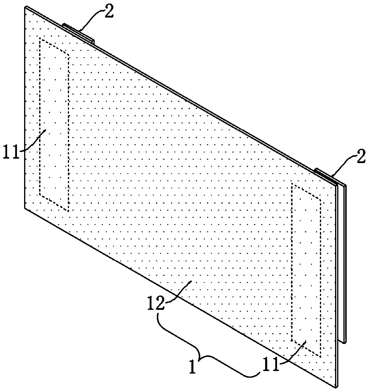
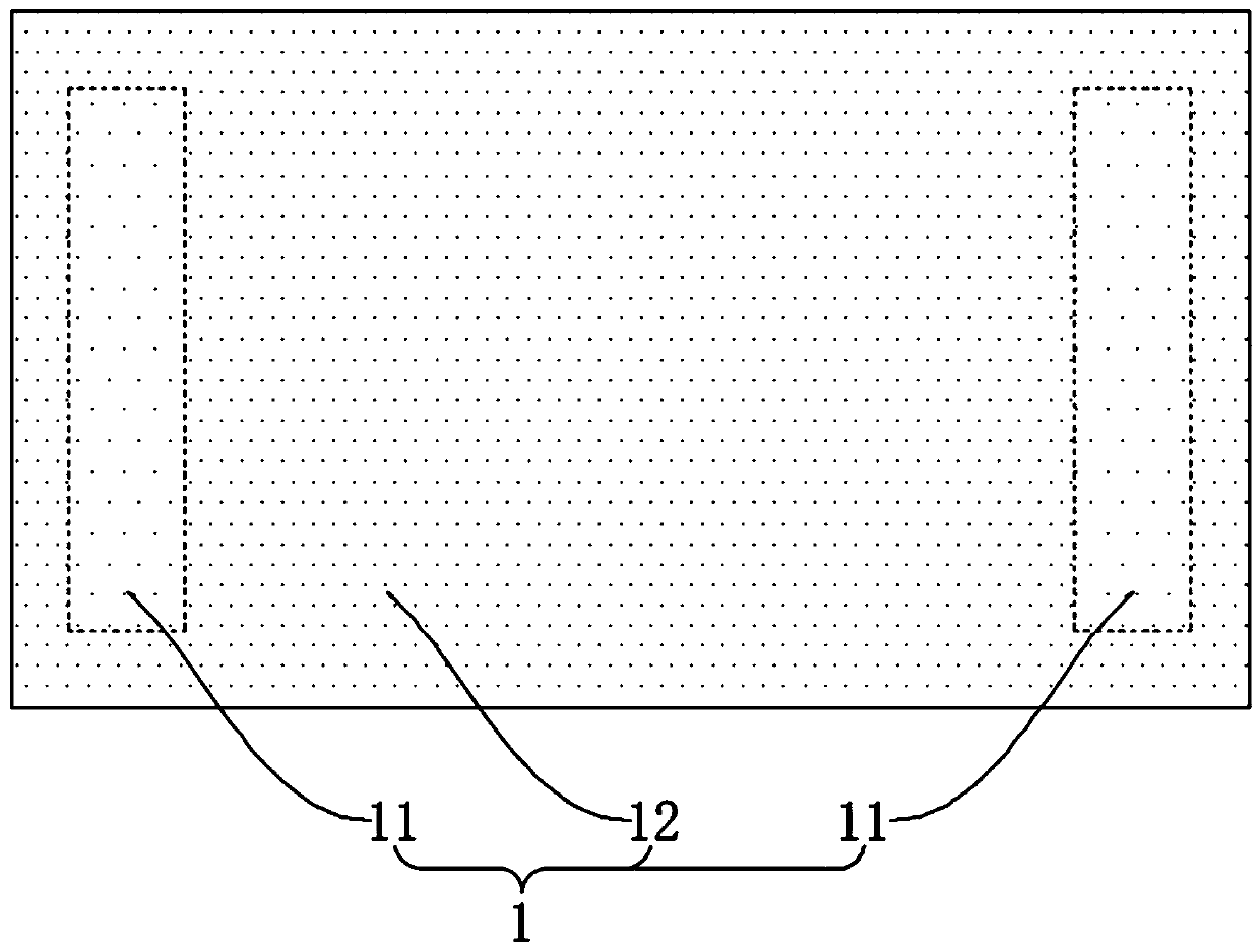
[0004] In order to solve the problem that the existing liquid crystal display screen is difficult to realize the narrow or ultra-narrow bezel design, and the screen-to-body ratio will always be affected by the GOA circuit, the present invention innovatively provides a display panel, a display device and electronic equipment, boldly The GOA circuit is set directly behind the effective display area, and effectively solves the influence of the GOA circuit on the LCD screen display in parallel, thereby realizing the premise of the normal display of the screen. Narrow bezel LCD screen design provides a new solution

Method used


Image

  • Display panel, display device and electronic equipment
  • Display panel, display device and electronic equipment
  • Display panel, display device and electronic equipment

Examples


Embodiment Construction

[0028] The technical solutions of a display panel, a display device and an electronic device provided by the present invention are clearly and completely described below in conjunction with the accompanying drawings of the specification. Obviously, the described embodiments are only a part of the embodiments of the present invention, rather than all of them. example. Based on the embodiments of the present invention, all other embodiments obtained by those skilled in the art without creative work shall fall within the protection scope of the present invention.

[0029] In the description of the present invention, it should be understood that the terms "center", "longitudinal", "transverse", "length", "width", "thickness", "upper", "lower", "front", " The orientation or positional relationship indicated by “rear”, “left”, “right”, “vertical”, “horizontal”, “top”, “bottom”, “inner” and “outer” are based on the orientation shown in the drawings Or the positional relationship is onl...


PUM


Abstract

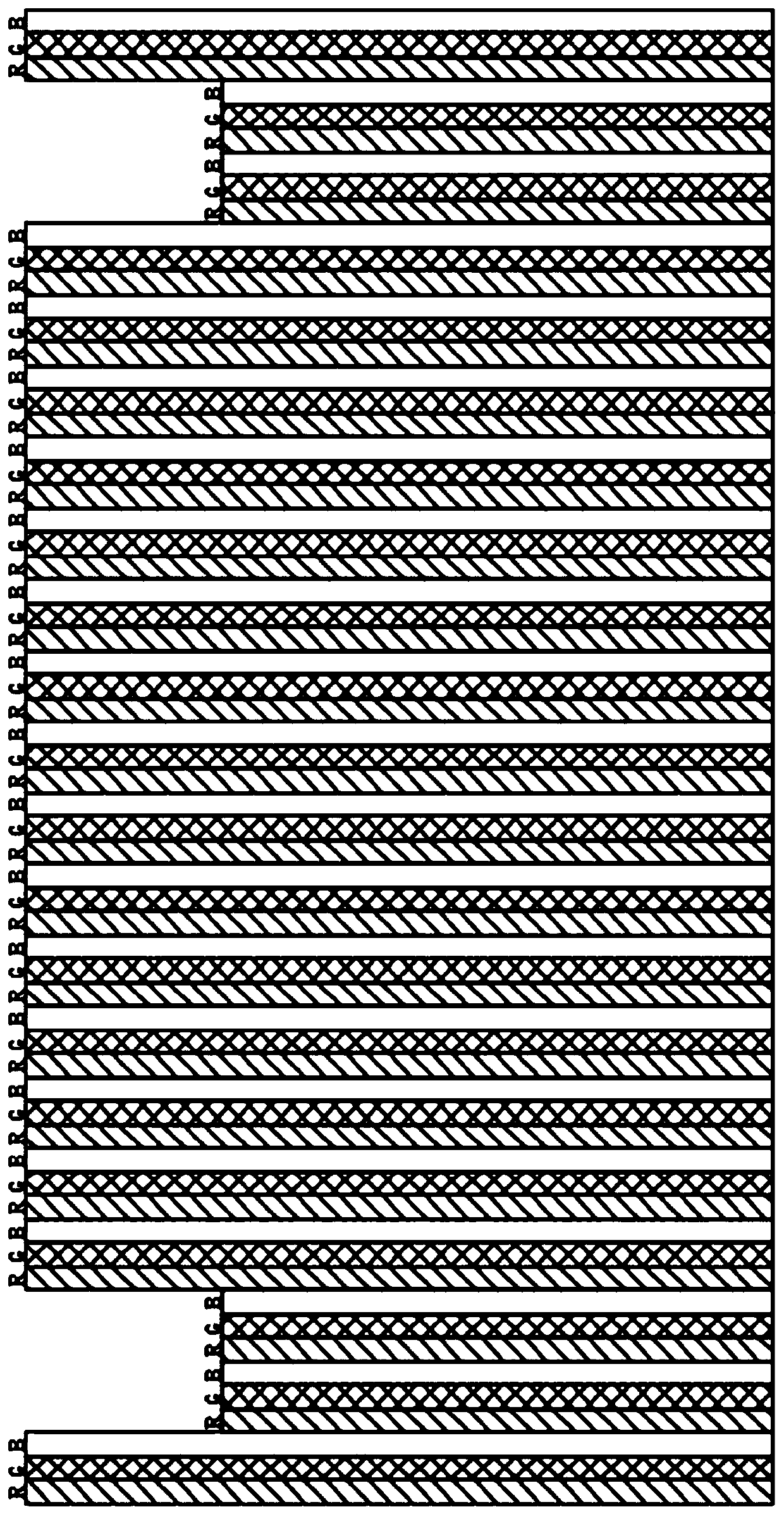
The invention discloses a display panel, a display device and electronic equipment. The display panel comprises an effective display area arranged on the upper surface of the display panel, a color filter and an array substrate row driving circuit, wherein the color filter and the array substrate row driving circuit are arranged right behind the effective display area. An area covered by an orthographic projection formed by the array substrate row driving circuit on the effective display area is a first display area; the first display area and the second display area beside the first display area can form an effective display area; wherein the color density of the color filter at any position or at part of the first display area range is lower than that of the color filter in the second display area range, the display device comprises the display panel, and the electronic equipment comprises the display device. The GOA circuit can be completely moved to the effective display area, theinfluence of the GOA circuit on normal display of the screen is thoroughly eliminated by adjusting the CF color concentration, and the brightness of the whole display screen seen by an observer is consistent.

Description

Technical field [0001] The present invention relates to the technical field of display panel design. More specifically, the present invention relates to a display panel, a display device and an electronic device. Background technique [0002] With the continuous development of display panel technology, especially the continuous development of liquid crystal display (LCD) with high-quality display, power saving, and thin thickness, compared with SOC (System On Chip) drive mode, GOA The driving method can achieve a narrower frame of the display panel, lower cost and can save the driver chip, so people began to use the array substrate row driver circuit (GOA circuit) more and more, that is to design the gate driver circuit directly on the array , Called Gate Driver on Array, or GOA for short. However, traditional GOA circuits are often placed next to the effective display area, that is, in the non-display area. This approach limits the development of narrow-edge and ultra-narrow-ed...

Claims


Application Information

Patent Timeline
Patent Type & Authority Applications(China)
IPC IPC(8): G02F1/1335G02F1/1333G02F1/1345
CPCG02F1/133514G02F1/133308G02F1/13454
Inventor 林永伦
Owner SHENZHEN CHINA STAR OPTOELECTRONICS SEMICON DISPLAY TECH CO LTD
Learn More