
Differential PLL with charge pump chopped wave function

A charge pump, charge pump technology, applied in the direction of automatic power control, conversion equipment without intermediate conversion to AC, electrical components, etc.

Active Publication Date: 2020-05-08
HUAWEI TECH CO LTD
View PDF13 Cites 2 Cited by
  • Summary
  • Abstract
  • Description
  • Claims
  • Application Information

AI Technical Summary

Problems solved by technology

However, such charge-pump-less circuits tend to occupy the low end of the PLL performance spectrum and require high-precision, high-current TDC circuits to improve performance

Method used


Image

  • Differential PLL with charge pump chopped wave function
  • Differential PLL with charge pump chopped wave function
  • Differential PLL with charge pump chopped wave function

Examples


Embodiment Construction

[0043] It should be understood at the outset that, although an illustrative implementation of one or more embodiments is provided below, the disclosed systems and / or methods may be implemented using any number of techniques, whether currently known or in existence. The invention should in no way be limited to the illustrative implementations, drawings, and techniques illustrated below, including the exemplary designs and implementations illustrated and described herein, but rather be within the scope of the appended claims and their equivalents Modified within the full range of .

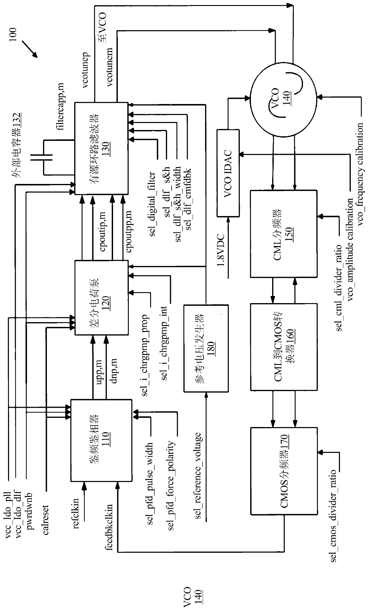
[0044] The so-called passive mode can be a conventional PLL that utilizes one or more external capacitors to achieve the desired loop dynamics. figure 1 A high-level schematic of a PLL 100 is shown, which can operate in a passive mode. The PLL circuit 100 includes a control path and a feedback path coupled to the control path. The control path may include a traditional three-state phase frequency ...


PUM


Abstract

According to a first example aspect there is provided a charge pump circuit that includes a first chopper circuit configured to switch first and second chopper circuit outputs between first and secondchopper circuit inputs at a chopping frequency, wherein successive input signals at the first chopper circuit input are output alternatively at the first and second chopper circuit outputs in successive cycles of the chopping frequency and successive input signals at the second chopper circuit input are output alternatively at the second and first chopper circuit outputs in successive cycles of the chopping frequency. A differential charge pump is configured to receive the signals output from the first and second chopper circuit output ends and produces corresponding first and second charge pumped signals.

Description

[0001] related application [0002] This application claims priority to earlier filed U.S. Provisional Patent Application No. 62 / 440,782, filed December 30, 2016, entitled "Differential PLL with Charge Pump Chopping," and filed on August 2017. Priority to Priority Application to U.S. Nonprovisional Patent Application No. 15 / 683,374, filed on 22nd, entitled "Differential PLL with Charge Pump Chopping," the entire contents of both patent applications are incorporated by reference Incorporated into this article. Background technique [0003] The phase of the output signal may be related to the phase of the input reference signal. The PLL circuit may include a phase frequency detector (PFD for short), a charge pump (CP for short), a loop filter, and a voltage-controlled oscillator (VCO for short). In use, the PFD may compare the phase of the input reference signal with the phase of a signal derived from the output of the VCO. The PLL can adjust the frequency of its oscillator o...

Claims


Application Information

Patent Timeline
IPC IPC(8): H03L7/06
CPCH03L7/0896H04B14/06H04L25/0272H04L25/085H04L27/0014H04L2027/0053H04L2027/0063H02M3/07H04L1/0029H04L2203/02H04B7/0641H03L7/0891H03L7/093H03L7/099
Inventor 德米特里·彼得罗夫
Owner HUAWEI TECH CO LTD
Learn More