Variable injection slider

A technology of injection block and slider, which is applied in the field of chemical experiments, can solve problems such as low efficiency, single injection method, and low injection efficiency, and achieve the effects of improved efficiency, various injection methods, and a wide range of applications

Inactive Publication Date: 2020-05-12
安徽奇书生物科技有限公司
View PDF17 Cites 0 Cited by
  • Summary
  • Abstract
  • Description
  • Claims
  • Application Information

AI Technical Summary

Problems solved by technology

[0003] The technical problem to be solved by the present invention is: in order to solve the problems existing in the above-mentioned background technology, an improved variable injection slider is provided to solve the problem that the slider in the traditional injection system cannot change the structure, the injection method is single, and the injection efficiency is low , the single limitation of experimental data, the problem of low efficiency

Method used


Image

  • Variable injection slider
  • Variable injection slider
  • Variable injection slider

Examples


Embodiment Construction

[0015] The present invention is described in further detail now in conjunction with accompanying drawing. These drawings are all simplified schematic diagrams, which only illustrate the basic structure of the present invention in a schematic manner, so they only show the configurations related to the present invention.

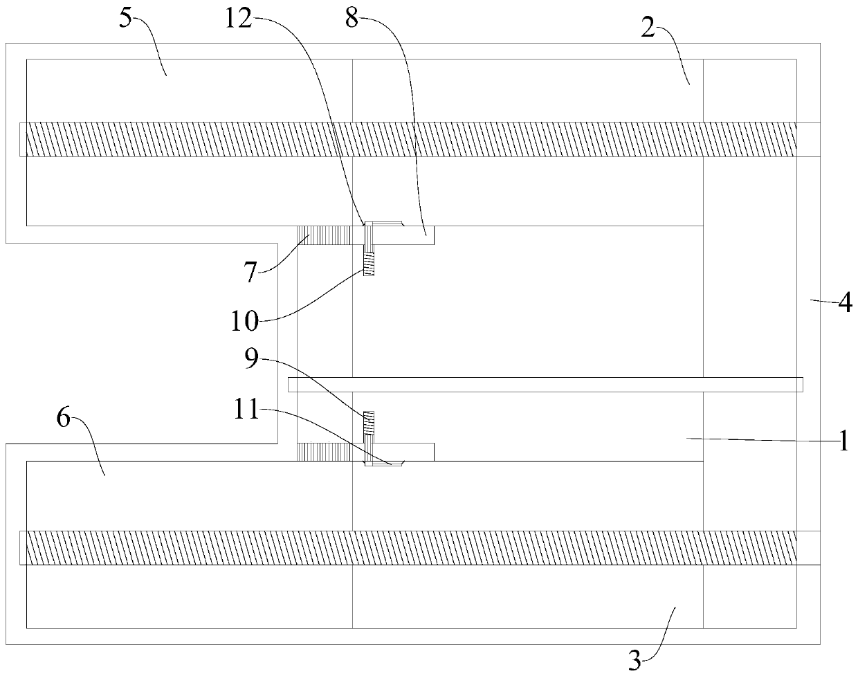
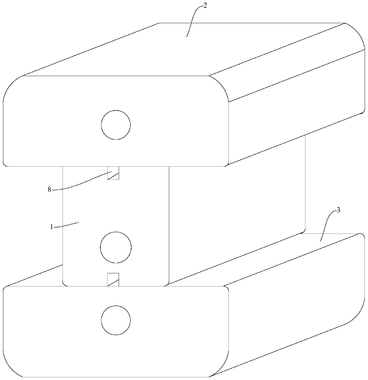
[0016] figure 1 and figure 2 A variable injection slider is shown, including a slider body and an external housing. The slider body includes a middle injection block 1, an upper injection block 2 connected to the upper end of the middle injection block 1, and an upper injection block connected to the middle injection block. The lower injection block 3 at the lower end of the injection block 1, the outer casing includes a main box body 4, an upper left injection box body 5 located at the left upper end of the main box body 4 and a left lower injection box body 6 located at the left lower end of the main box body 4, The upper end and the lower end of the inne...


PUM


Abstract

The invention relates to the technical field of chemical experiments, in particular to a variable injection slider which comprises a slider body and an outer shell. The slider body comprises a middleinjection block. The variable injection slider is formed by assembling a middle injection block, an upper injection block and a lower injection block. Transmission grooves internally provided with external thread telescopic limiting rods are formed in the upper end and the lower end of the left side face of the middle injection block correspondingly. A transmission rack on the inner wall of the left side of the outer shell is matched to be automatically separated from the upper injection block and the lower injection block when the middle injection block horizontally moves to a designated position, so that the structure of the injection slider can be separated and combined at the designated position according to needs, the application range is wider, injection modes are diversified, and efficiency is greatly improved.

Description

technical field [0001] The invention relates to the technical field of chemical experiments, in particular to a variable injection slider. Background technique [0002] As microfluidic chips are widely used in various chemical experiments and tests in recent years, in one experiment, the injection rate and sequence of injection of multiple drugs may be required, and sometimes several drugs must be realized during the experiment. Simultaneous injection in different proportions. Therefore, the performance requirements of the injection system are becoming more and more stringent. It is required that they can inject accurately according to the set injection rate, and it is also required that the operator can easily set up the cooperative work of each pump. However, the slider in the traditional injection system cannot change the structure, the injection method is single, the injection efficiency is low, and the experimental data is single and limited, so the efficiency is not hi...

Claims


Application Information

Patent Timeline
Patent Type & Authority Applications(China)
IPC IPC(8): B01L3/00B01L3/02F04B53/00F04B53/14F04B53/16
CPCB01L3/0217B01L3/5027F04B53/00F04B53/14F04B53/16
Inventor 张鹏成
Owner 安徽奇书生物科技有限公司
Why Eureka
Try Eureka