Cooling liquid jetting mechanism

A technology of spray mechanism and coolant, applied in metal processing machinery parts, maintenance and safety accessories, metal processing equipment, etc. There are no problems such as good cooling and lubrication, so as to achieve the effect of improving flexibility and versatility, various spraying methods, and avoiding the dead angle of spraying.

Active Publication Date: 2014-03-26
ANHUI QUANCHAI JINTIAN MASCH CO LTD
View PDF5 Cites 14 Cited by
  • Summary
  • Abstract
  • Description
  • Claims
  • Application Information

AI Technical Summary

Problems solved by technology

[0004] When the traditional cutting fluid pouring method is working, the cutting fluid mainly acts on chips, workpieces and cutter bodies, and where cooling and lubrication are most needed, the joints between the cutting edge and the workpiece, and the cutting edge and chips are not in place due to insufficient pouring and other reasons. not well cooled and lubricated
[0005] The development of metal cutting processing technology has always been carried out around the transformation of machine tool conditions, tool conditions and cooling conditions, but the lagging status of research on cooling conditions has actually been unable to meet the needs of the development of modern metal cutting processing technology

Method used


Image

  • Cooling liquid jetting mechanism
  • Cooling liquid jetting mechanism
  • Cooling liquid jetting mechanism

Examples


Embodiment Construction

[0025] The coolant injection mechanism of the present invention will be described in detail below in conjunction with the accompanying drawings.

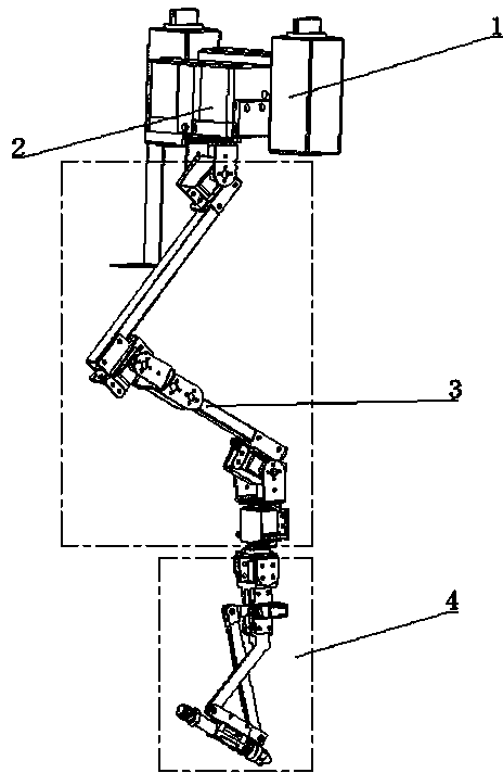
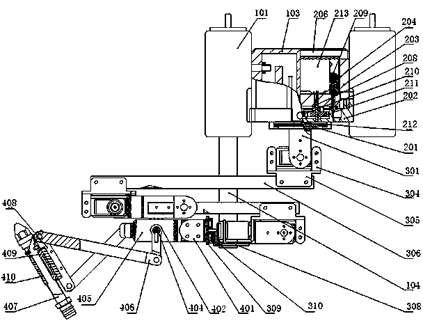
[0026] like figure 1 , figure 2 As shown, the coolant injection mechanism of the present invention includes four parts, which are sequentially connected from top to bottom: the adsorption base 1 , the main body frame 2 , the mechanical arm 3 and the swing head.

[0027] 1.1 Adsorption base structure

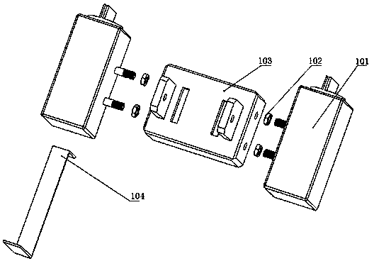
[0028] combine image 3 As shown, the design of the adsorption base 1 uses the adsorption principle of the magnetic watch base 101 to support the overall weight, including the hanger 104, the magnetic watch base 101 located at the left and right ends and the base 103 in the middle. The fastening between the base 103 and the magnetic watch base 101 is supported by four M8 nuts 102 . A groove is provided at the lower end of one of the magnetic watch bases; one end of the hanger 104 is inserted into the groove. The base 103 is p...


PUM


Abstract

The invention discloses a cooling liquid jetting mechanism which comprises an adsorption base, a main frame, a mechanical arm and a swing head. The two ends of the adsorption base are provided with magnetic meter bases. The main frame is connected with the adsorption base. One end of the mechanical arm is rotationally arranged at the lower end of the main frame and the other end of the mechanical arm is connected with the swing head. The swing head comprises a motor support, a swing servo steering engine, a nozzle and a swing mechanism. One end of the motor support is connected with the mechanical arm. The swing servo steering engine is fixed to the motor support. The nozzle is connected with an output shaft of the swing servo steering engine through the swing mechanism. The cooling liquid jetting mechanism can rotate around a main shaft by 360 degrees and jetting dead angles and dead zones are avoided; meanwhile, the mechanical arm with multiple freedom degrees is used so that the nozzle can be accurately located and flexibility and universality can be improved.

Description

technical field [0001] The invention relates to a cooling liquid injection mechanism, in particular to a cooling liquid injection mechanism used in the cooling system of a numerically controlled machine tool. Background technique [0002] Since the 20th century, fierce market competition has promoted the development of advanced manufacturing technology led by mechanical manufacturing technology at an unprecedented speed and breadth. High productivity and high quality are the two goals of advanced manufacturing technology. Therefore, the "green manufacturing" technology with rational use of resources, less pollution and less waste will become the mainstream of the 21st century. [0003] The cutting fluid mainly plays the role of lubrication, cooling, cleaning and rust prevention in the cutting process. In the metal cutting process, the cost related to the cutting fluid accounts for 5% to 30% of the entire processing cost (including waste oil treatment Fees, etc.), in ter...

Claims


Application Information

Patent Timeline
Patent Type & Authority Applications(China)
IPC IPC(8): B23Q11/10
CPCB23Q11/10
Inventor 宋海潮吴静
Owner ANHUI QUANCHAI JINTIAN MASCH CO LTD
Why Eureka
Try Eureka