A linear guide rail type cooling system control mechanism

A cooling system control, linear guide technology, applied in the direction of manufacturing tools, metal processing machinery parts, maintenance and safety accessories, etc., can solve the problem of affecting the flexibility of the tool, easy to cause interference, etc. The effect of reducing usage

Active Publication Date: 2017-03-08
NANJING VOCATIONAL UNIV OF IND TECH
View PDF8 Cites 0 Cited by
  • Summary
  • Abstract
  • Description
  • Claims
  • Application Information

AI Technical Summary

Problems solved by technology

However, the increase of more complex mechanisms will affect the flexibility of the cutting tool and easily cause interference

Method used


Image

  • A linear guide rail type cooling system control mechanism
  • A linear guide rail type cooling system control mechanism
  • A linear guide rail type cooling system control mechanism

Examples


Embodiment Construction

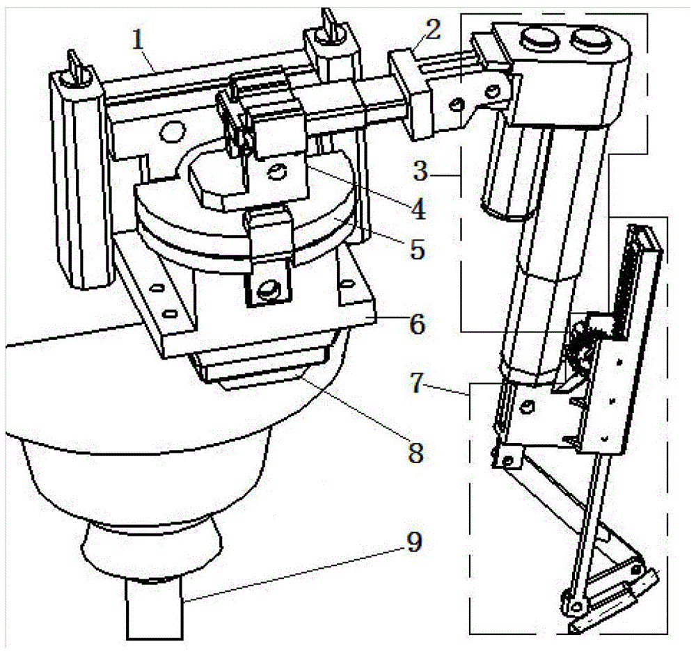
[0026] A linear guide rail type cooling system control mechanism, including a base 1, a swing arm 2, a telescopic arm 3, a rotating bracket 4, a fixed frame 6, a swing head 7 and a servo motor 8, the base is fixed on the machine tool, and the fixed frame is installed on the base , the servo motor is fixed on the fixed frame, and the rotary bracket connected with the servo motor is rotatably arranged on the fixed frame; one end of the swing arm is fixed on the rotary frame, and the other end is connected with the telescopic arm that can move up and down; the swing head is set on The top of the swing arm; the swing head is provided with a spray nozzle 77.

[0027] Such as figure 1 As shown in the figure, the cutter 9 and the base 1 are fixed on the machine tool, the servo motor 8 is fixed on the fixed frame 6, and the fixed frame 6 is installed on the base 1; the rotating bracket 4 is connected with the fixed frame cover 5 through the bearing; the swing arm 2 Fixed on the rotat...


PUM


Abstract

The invention discloses a linear guide rail type cooling system control mechanism, which comprises a base, a swing arm, a telescopic arm, a rotating bracket, a fixed frame, a swing head and a servo motor. The base is fixed on a machine tool, the fixed frame is installed on the base, and the servo motor Fixed on the fixed frame, the rotating bracket connected with the servo motor is rotatably set on the fixed frame; one end of the swing arm is fixed on the rotating bracket, and the other end is connected with the telescopic arm that can move up and down; the swing head is set on the swing arm Top; sprinkler head is provided on the swing head. The invention realizes the 180° rotation of the spray head around the tool through the linear guide rail mechanism, reduces the volume of the mechanism, and realizes all-round spraying; controls the orientation and rotation of the spray head through the four-bar mechanism, reduces the number of spray heads, reduces the usage of coolant, and realizes no dead angle Jet, greatly improve the cooling effect.

Description

technical field [0001] The invention relates to a tool cooling device for a numerically controlled machine tool, in particular to a linear guide rail type cooling system control mechanism. Background technique [0002] CNC machine tool tools tend to generate high temperature when they work for a long time and reduce their service life. In traditional use, the cooling effect is generally regarded as a proportional relationship with the amount of cutting fluid. Therefore, the pouring method is largely a reflection of this thinking. In the actual use process, when the cooling effect of the cutting fluid is not as good as expected, the amount of cutting fluid used is often increased. As a result, not only cannot solve the cooling problem, but also bring about the consequences of increased pollution. [0003] For example, Chinese patent, application number: 201320607230.5, title of invention: a ring-shaped universal cooling nozzle for CNC machine tools. A number of spray bodies e...

Claims


Application Information

Patent Timeline
Patent Type & Authority Patents(China)
IPC IPC(8): B23Q11/10
CPCB23Q11/10Y02P70/10
Inventor 宋海潮王晓勇甄久军徐峰周玲吴静
Owner NANJING VOCATIONAL UNIV OF IND TECH
Why Eureka
Try Eureka