Water conservancy irrigation device
An irrigation device and water conservancy technology, applied in watering devices, gardening, botany equipment and methods, etc., can solve problems such as changing the distance between sprinklers, clogging irrigation sprinklers, and insufficient nozzles.
- Summary
- Abstract
- Description
- Claims
- Application Information
AI Technical Summary
Problems solved by technology
Method used
Image
Examples
Embodiment 1
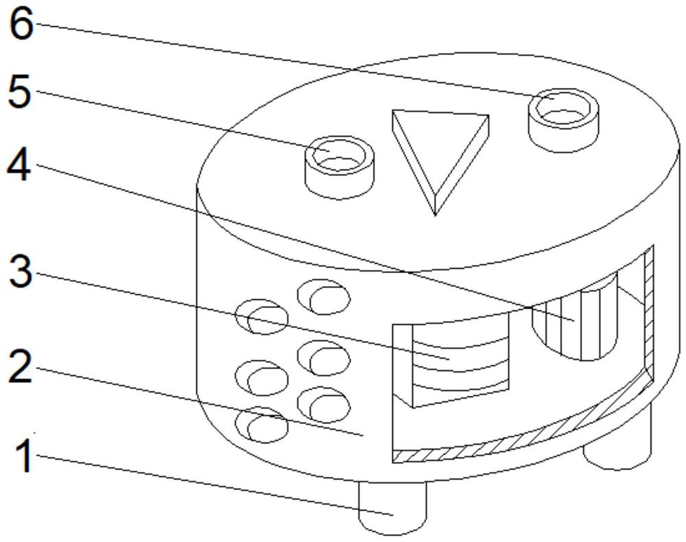
[0033] See Figure 1-2 The present invention provides a technical solution: a water conservancy irrigation device, including the container can 2, the bottom filter layer of the container can 2 is fixedly connected to the support column 1, and the intermediate position of the bottom left side of the container can 2 is connected to the water pipe 5, The intermediate position of the upper right side of the upper right side of the container can 2, and the inner chamber of the container can 2 is fixed to the connection of the irrigation device 3, and the lumen bottom of the container can 2 is fixed to the right side of the irrigation device 3. Box 4.
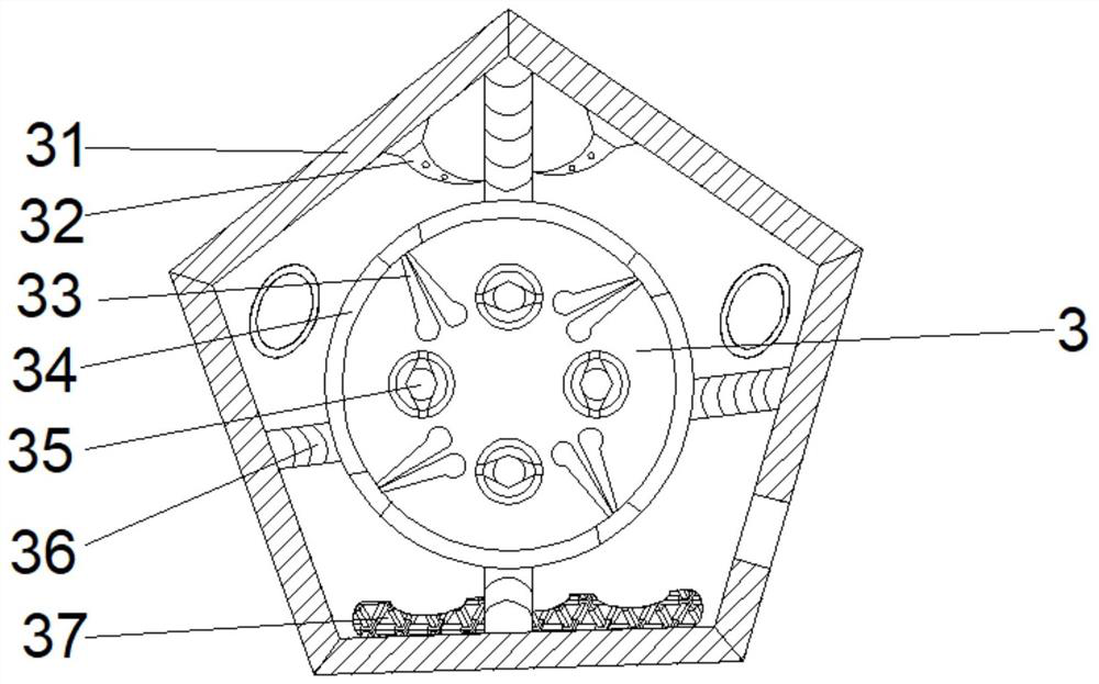
[0034] Among them, the irrigation device 3 includes a storage tank 31, and a fixed bar 36 is fixedly attached to the middle of the inner wall of the storage tank 31, and the fixing rod 36 is fixedly connected to one end of the storage tank 31 fixed to the storage tank 34, two of the water tank 34. The inner walls are fixedly connected to ...
Embodiment 2
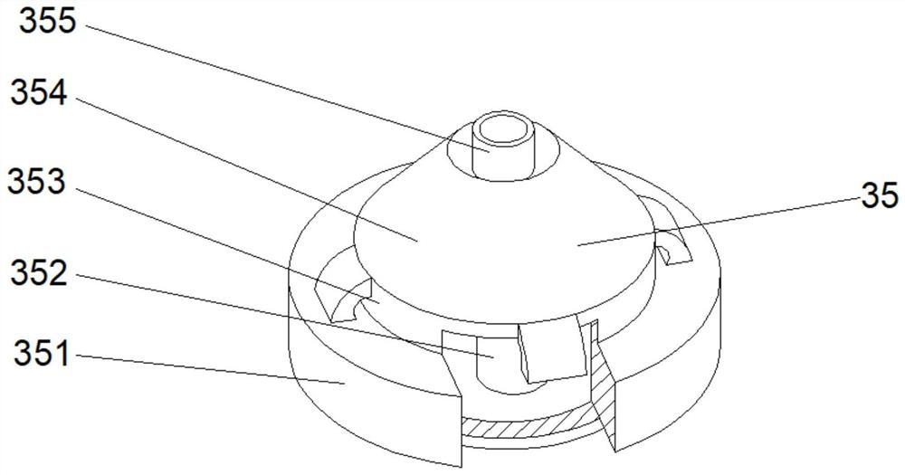
[0037] See Figure 1-4 On the basis of the first example, the present invention provides a technical solution: the injection mechanism 35 includes a housing 353, and the intermediate portion of the outer surface of the casing 353 is fixedly coupled with the linkage ring 351, and the top fixed connection of the housing 353 has a dredge mechanism 354. The intermediate position of the dredge mechanism 354 communicates with the injection head 355, the intermediate position of the inner chamber bottom of the casing 353, and the top portion of the flow tube 352 communicates with the dredge mechanism 354.
[0038] Wherein, the dredge mechanism 354 includes an inlet D1, the bottom intermediate position of the inlet port D1 is fixedly connected to the squeezing rod D4, and the bottom end of the pressing rod D4 is fixedly connected to the squeezing ball D5, and the bottom of the inlet D1 is located in the squeezing rod D4. The outer dosing plate D3 is provided on both sides, and the outer do...
Embodiment 3
[0041] See Figure 1-6 In the basis of the first embodiment, the present invention provides a technical solution: the auxiliary mechanism D2 includes a guard D21, and the bottom left side of the guard plate D21 is fixedly connected to the auxiliary panel D25, the top of the top of the auxiliary panel D25. The fixed connection block D24 is fixed to the right side of the reset block D24, and the bond block D22 is fixed, and the right side of the bond block D22 is connected to the separator D23.
[0042] Wherein, the auxiliary panel D25 includes a plate T1, and the right side of the plate body D1 is fixedly connected to the right side of the outer contact plate T2 externally, and the tank T3 is opened.
[0043] When used, the incontinated groove T3 can facilitate fixation, so that the device is tightly bonded, which can effectively speed up the flow discharge from the inside, further increase the convenience of the device, avoid the speed of the device to move the device excessive imp...
PUM
 Abstract
Description
Claims
Application Information
 - R&D
- Intellectual Property
- Life Sciences
- Materials
- Tech Scout
- Unparalleled Data Quality
- Higher Quality Content
- 60% Fewer Hallucinations
Browse by: Latest US Patents, China's latest patents, Technical Efficacy Thesaurus, Application Domain, Technology Topic, Popular Technical Reports.
© 2025 PatSnap. All rights reserved.Legal|Privacy policy|Modern Slavery Act Transparency Statement|Sitemap|About US| Contact US: help@patsnap.com


