
Water quality sample injecting method, analyzing method and device

A technology for water quality analysis and sample injection, which is used in material analysis, measurement devices, and analysis materials by optical means. The effect of reducing reagent consumption and reducing maintenance workload

Inactive Publication Date: 2011-06-22
FOCUSED PHOTONICS +2
View PDF6 Cites 3 Cited by
  • Summary
  • Abstract
  • Description
  • Claims
  • Application Information

AI Technical Summary

Problems solved by technology

[0007] 1) The injection volume depends on the volume of the quantitative chamber of the quantitative slide valve. For a certain type of quantitative slide valve, the volume of the quantitative chamber is fixed, and the quantitative volume cannot be adjusted, so that the injection volume cannot be adjusted. The measurement of changing the injection volume cannot be realized;
[0008] 2) For long-term use, pollutants will accumulate inside the quantitative chamber, making the quantitative volume inaccurate and affecting the analysis results. Therefore, the quantitative chamber needs to be cleaned regularly, which is inconvenient to use and maintain;
[0009] 3) When the sample is injected through the quantitative chamber, there will be residues on the inner wall of the sampling chamber, which makes the small volume injection inaccurate and further affects the accuracy of subsequent analysis results
[0014] 1) The injection volume depends on the volume of the quantitative loop. For the situation where the injection volume needs to be changed for measurement, the quantitative loop must be replaced manually, which is troublesome to operate;
[0015] 2) If there is a dead volume in the channel inside the solenoid valve, reagent residues are prone to occur, and the residual sample from the previous time is likely to interfere with the measurement of the next sample, thereby affecting the accuracy of the measurement result;
[0016] 3) When the sample is injected through the quantitative loop, there will be residues on the inner wall of the quantitative loop and the pipeline, which makes the small volume injection inaccurate and further affects the accuracy of subsequent analysis results

Method used

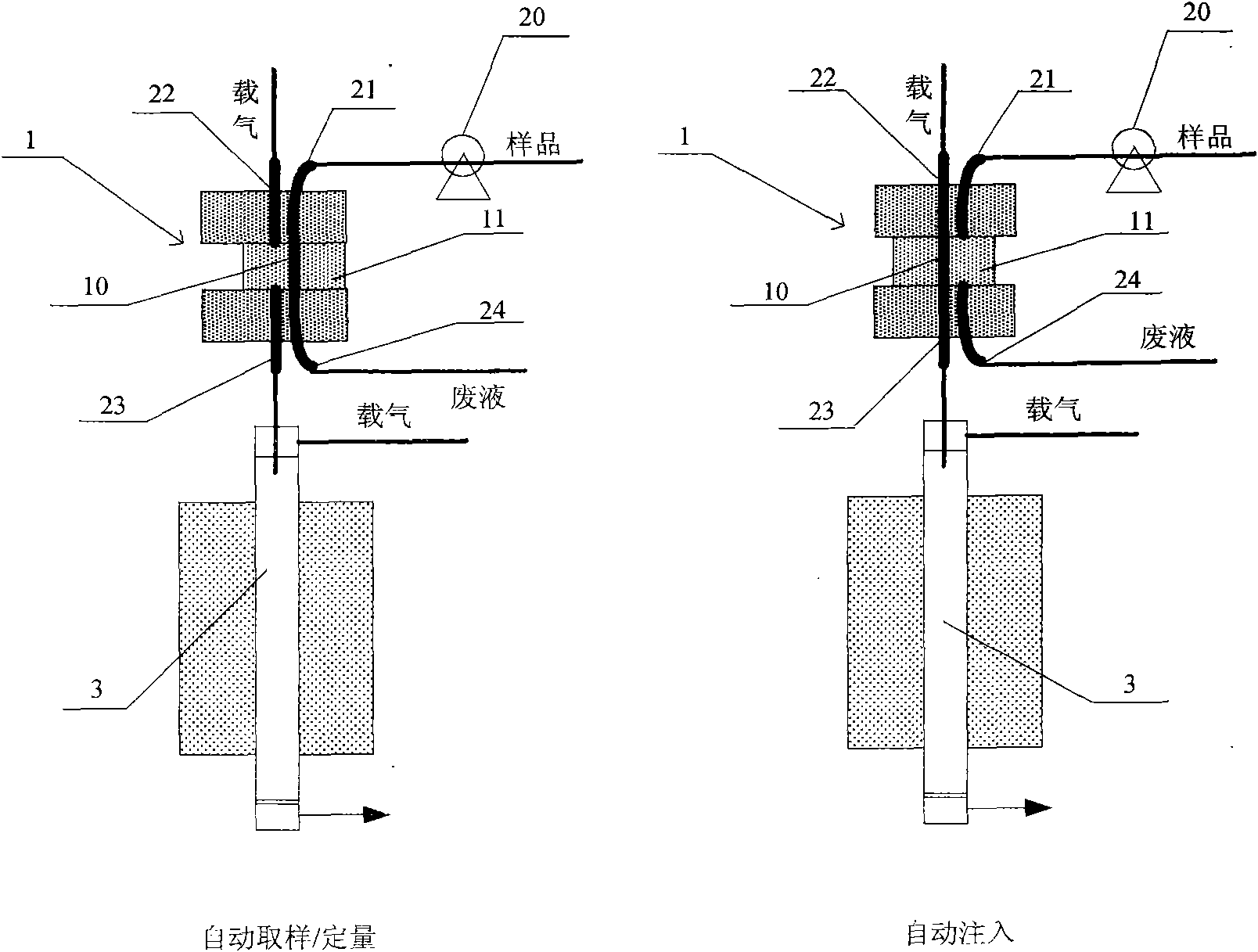
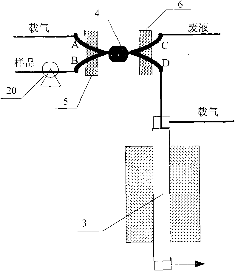

Image

  • Water quality sample injecting method, analyzing method and device
  • Water quality sample injecting method, analyzing method and device
  • Water quality sample injecting method, analyzing method and device

Examples


Embodiment 1

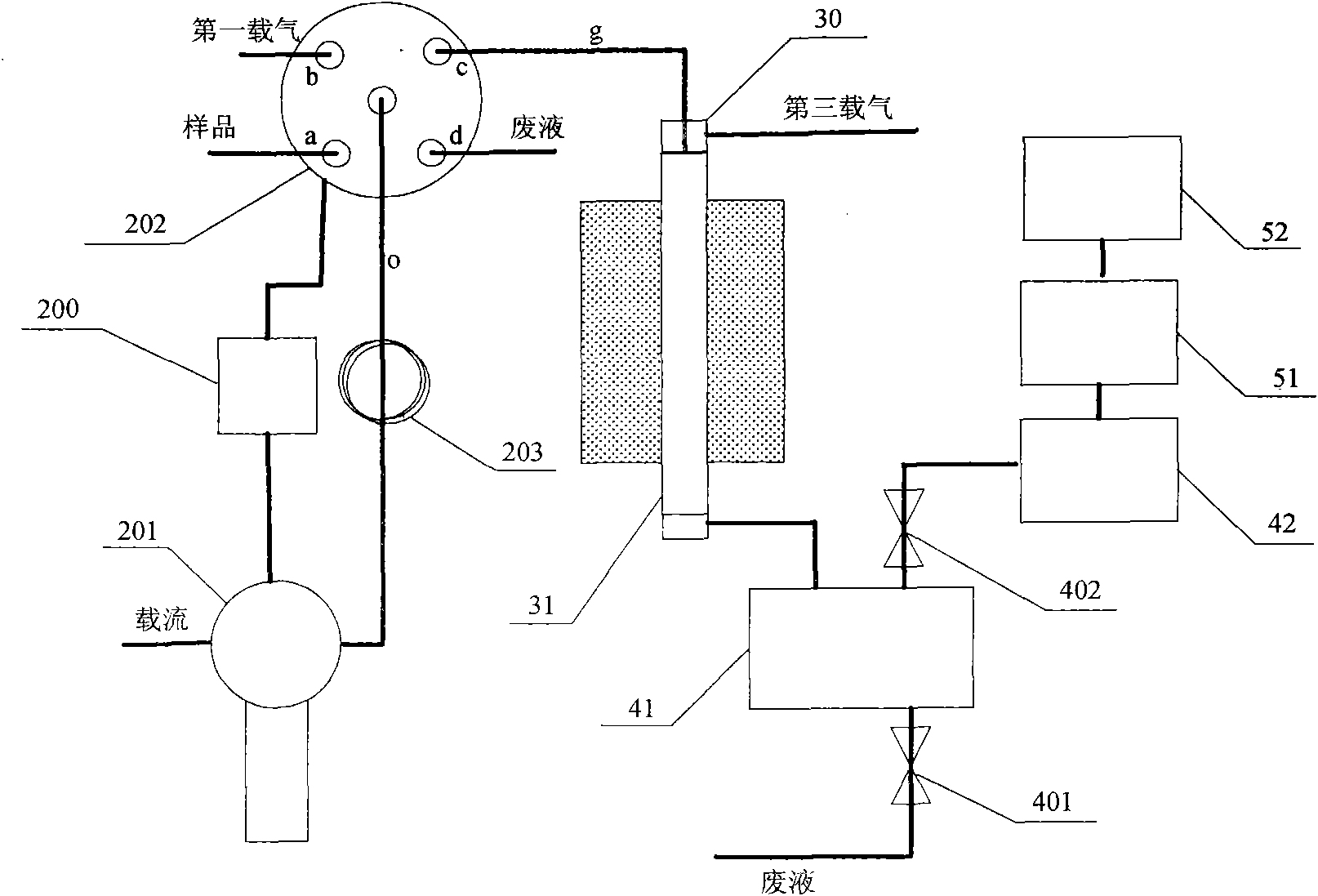
[0065] Such as image 3As shown, a water quality analysis device is used for total carbon analysis in water bodies, including a sampling unit, a control module 200, a reaction unit, a purification unit and a detection unit; the sampling unit is connected to a sample and a reagent, and the reagent Including the first carrier gas, the second carrier gas and the carrier flow;

[0066] The sampling unit includes a syringe pump 201, a multi-channel selector valve 202, a liquid storage ring 203 and pipelines;

[0067] One end of the syringe pump 201 is connected to the carrying current, and the other end is connected to the liquid storage ring 203 to accurately quantify the pumped substance; the carrying current can be distilled water or pure water with very low carbon content, and the carrying current in this embodiment is pure water;

[0068] The other end of the liquid storage ring 203 is connected with the multi-channel selector valve 202, and is used for temporarily storing t...

Embodiment 2

[0105] A water quality analysis device, used for total carbon analysis in water bodies, is the same as the water quality analysis device described in Example 1.

[0106] This embodiment also provides a water quality sampling method, which is different from the sampling method described in Example 1:

[0107] 1. In step A2, the control module 200 controls the syringe pump 201 to draw 100 μl of the carrier fluid into the liquid storage ring 203; and push the 100 μl carrier fluid through the injection channel c into the sample injection pipeline g for temporary storage;

[0108] 2. The sample injection method of the present embodiment also includes step A3, specifically:

[0109] The control module 200 controls the multi-channel selector valve 202 to select the carrier gas channel b, and the syringe pump 201 draws 1000 μl of the second carrier gas, namely air, into the liquid storage ring 203;

[0110] The control module 200 controls the multi-channel directional valve 202 to se...

Embodiment 3

[0115] A water quality analysis device, used for total carbon analysis in water bodies, is the same as the water quality analysis device described in Example 2.

[0116] This embodiment also provides a water quality sampling method, which is different from the water quality sampling method in Example 2:

[0117]1. Step A2 is to inject the first carrier gas into the sampling pipeline: the control module 200 controls the multi-channel selector valve 202 to select the carrier gas channel b, and the syringe pump 201 draws 50 μl of the first carrier gas, namely air, into the liquid storage ring 203 ;

[0118] The control module 200 controls the multi-channel selector valve 202 to select the injection channel c, and the syringe pump 201 pushes the air to push the air in the liquid storage ring 203 to the sample injection pipeline g through the injection channel c for temporary storage;

[0119] 2. Step A3 is to inject the carrier current into the sample injection pipeline and injec...


PUM


Abstract

The invention relates to a sample injecting method, comprising the step of injecting a sample and a reagent into a sample injecting pipeline. The reagent comprises a carrying current, the carrying current pushes the sample out from the sample injecting pipeline, and the sample enters into a downstream sample injecting port. The invention also provides a water quality analyzing method and device. The invention has the advantages of accurate sample injecting and simple operation.

Description

technical field [0001] The invention relates to a water quality total carbon or organic carbon sampling and analysis method and device, in particular to a water total carbon / total organic carbon sampling, analysis method and device. Background technique [0002] Total carbon (TC) in water includes total inorganic carbon (TIC) and total organic carbon (TOC). Total organic carbon in water is a direct representation of the total content of organic matter based on the carbon content in the water sample, and is one of the comprehensive indicators for evaluating the degree of organic matter pollution in water quality. The common analysis steps of total carbon (or total organic carbon) are: first inject a certain volume of water sample into the reaction unit, perform oxidation treatment, convert the total carbon or organic carbon in the water sample into carbon dioxide, and then detect the reaction Generated carbon dioxide concentration, and then calculate the total carbon or orga...

Claims


Application Information

Patent Timeline
IPC IPC(8): G01N21/00G01N21/01G01N1/28
Inventor 唐小燕项光宏
Owner FOCUSED PHOTONICS
Learn More