
Self-generating glow stick

A fluorescent stick and self-generating technology, applied in the field of entertainment equipment, can solve problems such as interference, damage to aesthetics, and complex structures

Inactive Publication Date: 2020-05-22
王浩怡
View PDF5 Cites 2 Cited by
  • Summary
  • Abstract
  • Description
  • Claims
  • Application Information

AI Technical Summary

Problems solved by technology

[0003] Most of the existing fluorescent sticks are composed of plastic tubes and glass tubes filled with different liquids. When in use, lightly bend the fluorescent sticks, break the glass tubes in the plastic tubes, and shake them gently to make the two liquids fully Mixed to achieve the best glow effect, but this kind of light stick can only be used once; there are also light sticks in the form of LED lights powered by batteries, which not only consume batteries, but also the frequency of LED lights flashing makes fixed It is impossible to perform rhythm according to the rhythm of the concert site, and even destroy the aesthetic feeling created by the individual melodies; there are also a few concerts that use a kind of light stick that can be controlled by the console, which is not only complicated in structure, but also expensive in equipment. At the same time, the signal from the console may cause interference to the surrounding electronic equipment. For example, in 2017, Bibi Zhou’s tour concert was held at the Zhuankou Sports Center. The car owner who came to watch the show found that the car could not be locked remotely

Method used


Image

  • Self-generating glow stick
  • Self-generating glow stick
  • Self-generating glow stick

Examples


Embodiment Construction

[0020] The following will clearly and completely describe the technical solutions in the embodiments of the present invention with reference to the accompanying drawings in the embodiments of the present invention. Obviously, the described embodiments are only some, not all, embodiments of the present invention.

[0021] In describing the present invention, it should be understood that the terms "upper", "lower", "front", "rear", "left", "right", "top", "bottom", "inner", " The orientation or positional relationship indicated by "outside", etc. is based on the orientation or positional relationship shown in the drawings, and is only for the convenience of describing the present invention and simplifying the description, rather than indicating or implying that the referred device or element must have a specific orientation, so as to Specific orientation configurations and operations, therefore, are not to be construed as limitations on the invention.

[0022] refer to Figure ...


PUM


Abstract

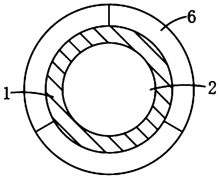
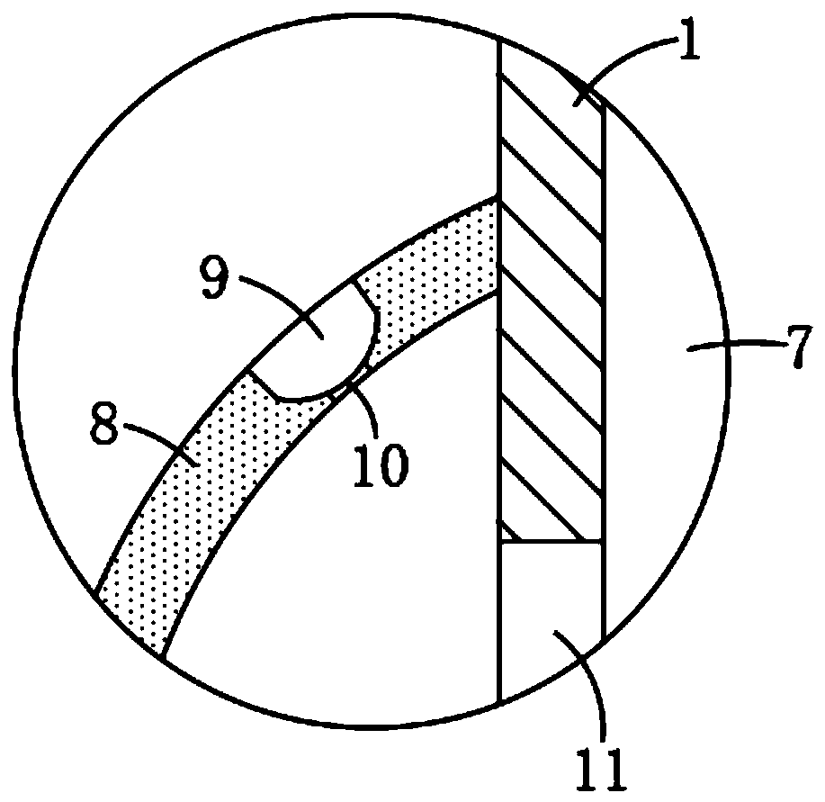
The invention discloses a self-generating glow stick. The glow stick comprises a glow stick body, a strip-shaped cavity is formed on the side wall of the glow stick body, and a magnetic block is connected in the strip-shaped cavity in a sealed and sliding manner and is elastically connected to the inner bottom of the strip-shaped cavity through a spring; a first air hole communicated with the interior of the strip-shaped cavity is formed at the upper end of the glow stick body, a spiral coil is embedded in the glow stick body, and an LED lamp tube is installed on the side wall of the glow stick body. According to the invention, when the audiences wave the glow sticks along with the music rhythm, the magnetic block continuously enters and exits from the spiral coil, so that the spiral coilintermittently cuts the magnetic induction lines of the magnetic block, and an induction current is intermittently generated in the spiral coil, and accordingly the LED lamp tube coupled with the spiral coil flickers. The self-generating glow stick can be matched with the music to generate a coordinated lighting effect, and the atmosphere of a concert is effectively highlighted.

Description

technical field [0001] The invention relates to the technical field of entertainment equipment, in particular to a self-generating fluorescent stick. Background technique [0002] Light sticks mostly appear in concerts or concerts, and the audience wave the light sticks according to the melody rhythm of the music to match the performance of the performers and play a role in setting off the atmosphere. [0003] Most of the existing fluorescent sticks are composed of plastic tubes and glass tubes filled with different liquids. When in use, lightly bend the fluorescent sticks, break the glass tubes in the plastic tubes, and shake them gently to make the two liquids fully Mixed to achieve the best glow effect, but this kind of light stick can only be used once; there are also light sticks in the form of LED lights powered by batteries, which not only consume batteries, but also the frequency of LED lights flashing makes fixed It is impossible to perform rhythm according to the ...

Claims


Application Information

Patent Timeline
IPC IPC(8): F21L13/00F21V23/02F21V33/00F21Y115/10
CPCF21L13/00F21V23/02F21V33/0004F21Y2115/10
Inventor 王浩怡徐若琛
Owner 王浩怡
Learn More