Mechanical interlocking device of isolation switch and breaker

A technology of isolating switches and interlocking devices, which is applied in the direction of electric switches, circuits, electrical components, etc., can solve problems such as inability to operate three-position isolating switches, misoperation, and large difference circuit breakers, and achieve the effect of timely unlocking

Pending Publication Date: 2020-05-22
CHINT ELECTRIC
View PDF0 Cites 1 Cited by
  • Summary
  • Abstract
  • Description
  • Claims
  • Application Information

AI Technical Summary

Problems solved by technology

As the core components of the gas insulated switchgear, the three-position isolating switch and vacuum circuit breaker play an important role in the control, protection, isolation and grounding functions of the switchgear. There must be a perfect equipment between the three-position isolating switch and the circuit breaker. The interlock device can ensure the reliable operation of electrical equipment. The switchgear equipped with an interlock mechanism can only operate the three-position isolating switch when the circuit breaker is open, and cannot operate the three-position isolating switch when the circuit breaker is closed.
However, the interlocking device between the three-position isolating switch and the circuit breaker of the existing switchgear is not perfect, and lacks a mechanical interlocking device, especially because of the differences in the circuit breaker, the mechanical interlocking structure and connection There is a large difference in the way and lack of mechanical interlocking effect on the circuit breaker, which can only be realized by electrical interlocking. In this way, in the absence of electrical interlocking protection, it will cause misoperation due to the lack of mechanical interlocking safety incident

Method used


Image

  • Mechanical interlocking device of isolation switch and breaker
  • Mechanical interlocking device of isolation switch and breaker
  • Mechanical interlocking device of isolation switch and breaker

Examples


Embodiment Construction

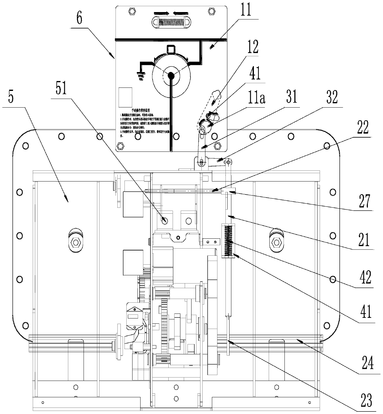
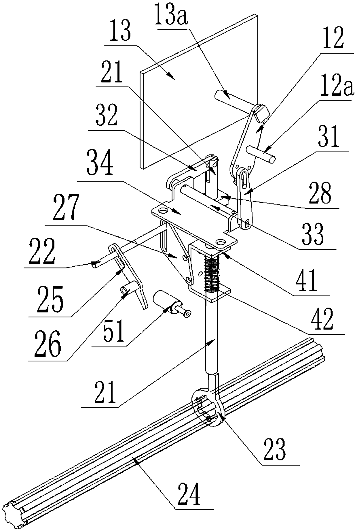
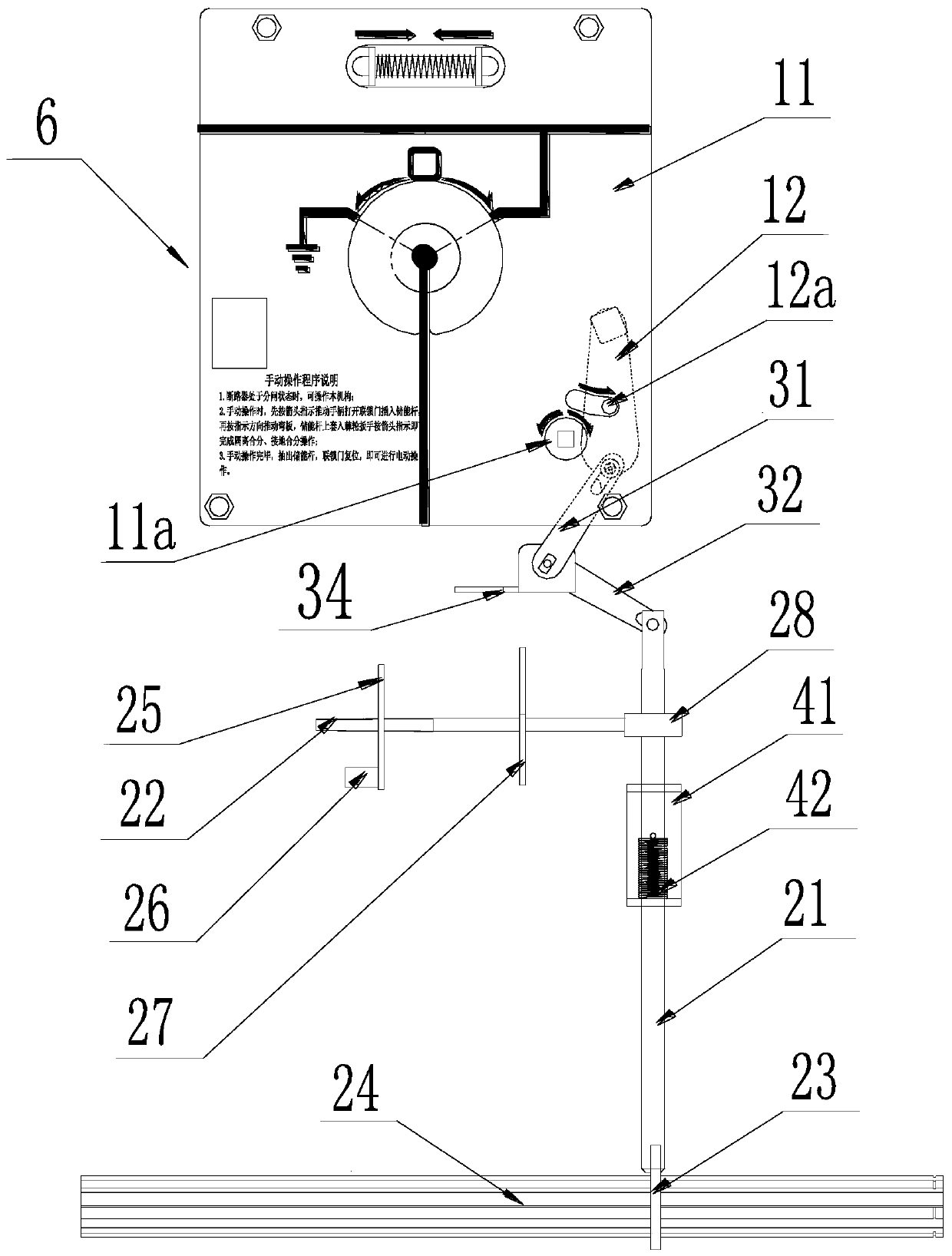
[0026] The following is attached Figures 1 to 9 The given examples further illustrate the specific implementation of a mechanical interlocking device for an isolating switch and a circuit breaker of the present invention. A mechanical interlocking device for an isolating switch and a circuit breaker of the present invention is not limited to the description of the following embodiments.

[0027] A mechanical interlock device for an isolating switch and a circuit breaker, including a baffle assembly, an interlock mechanism and an interlock mechanism; the baffle assembly includes a panel 11 and a movable baffle 12 of the isolating switch 6, and a useful In the operation hole 11a where the operation handle is inserted, the movable baffle 12 is rotatably installed and can expose or cover the operation hole 11a; the interlock mechanism includes a crank arm 23 and a first interlock lever 21, and the crank arm 23 is set On the transmission shaft 24, the crank arm 23 can be limitedl...


PUM


Abstract

A mechanical interlocking device of an isolating switch and a breaker comprises a baffle assembly, an interlocking mechanism and an interlocking mechanism. The baffle plate assembly comprises a panelof the isolation switch and a movable baffle plate. The panel is provided with an operation hole which can be shielded by the movable baffle plate. The interlocking mechanism comprises a crank arm anda first interlocking rod, the crank arm is arranged on the transmission shaft, the crank arm can be driven by the transmission shaft to be in limiting fit with the first interlocking rod, a second interlocking rod is fixedly arranged on the first interlocking rod, and a locking piece is arranged on the second interlocking rod; and when the circuit breaker is in a switching-off state, the first interlocking rod and the crank arm are not in limiting fit, the movable baffle is opened and exposed out of the operation hole, and the locking piece enables the circuit breaker not to be switched on. When the circuit breaker is in a closing state, the first interlocking rod is in limiting fit with the crank arm, the movable baffle is closed and shields the operation hole, and the locking piece andthe closing coil are unlocked. The mechanical interlocking device is of a mechanical structure, and the locking function can still be achieved even under the condition that electric interlocking doesnot exist.

Description

technical field [0001] The invention relates to a mechanical interlocking device of a high-voltage switchgear, in particular to a mechanical interlocking device of an isolating switch and a circuit breaker. Background technique [0002] Gas-insulated switchgear gathers medium-voltage components such as busbars, circuit breakers, and isolating switches in the box, and is widely used because of its good safety, high reliability, and strong adaptability. As the core components of the gas insulated switchgear, the three-position isolating switch and vacuum circuit breaker play an important role in the control, protection, isolation and grounding functions of the switchgear. There must be a perfect equipment between the three-position isolating switch and the circuit breaker. The interlock device can ensure the reliable operation of electrical equipment. The switchgear equipped with an interlock mechanism can only operate the three-position isolating switch when the circuit break...

Claims


Application Information

Patent Timeline
Patent Type & Authority Applications(China)
IPC IPC(8): H01H9/26
CPCH01H9/26
Inventor 王广先黄强赵瑞影程相浩罗天赐
Owner CHINT ELECTRIC
Why Eureka
Try Eureka