
An Angle Adjustment Structure for a Monitoring Probe

An angle adjustment structure and monitoring probe technology, applied in the field of monitoring probes, can solve problems such as dust contamination and impact on monitoring clarity

Active Publication Date: 2021-11-16
苏州市相城区渭塘城乡发展有限公司
View PDF13 Cites 0 Cited by
  • Summary
  • Abstract
  • Description
  • Claims
  • Application Information

AI Technical Summary

Problems solved by technology

[0003] And for example, in the patent application for an angle-adjustable monitoring camera with the patent application number CN201810747576.2, the direction of the monitoring probe is adjusted, and in order to improve its monitoring effect, sometimes its angle needs to be adjusted. , so that it can observe more angles, and when the monitoring probe is monitoring outdoors, its surface will be contaminated with a lot of dust, which will greatly affect the clarity of its monitoring. It is necessary to propose a monitoring Probe with angle adjustment structure

Method used


Image

  • An Angle Adjustment Structure for a Monitoring Probe
  • An Angle Adjustment Structure for a Monitoring Probe
  • An Angle Adjustment Structure for a Monitoring Probe

Examples


Embodiment 1

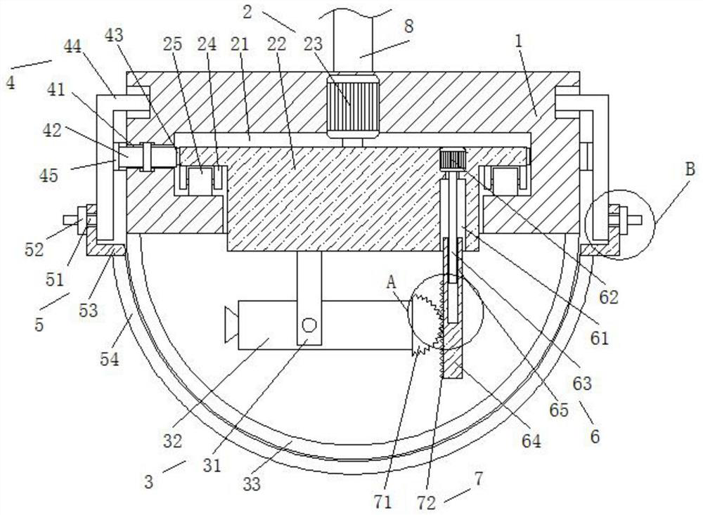
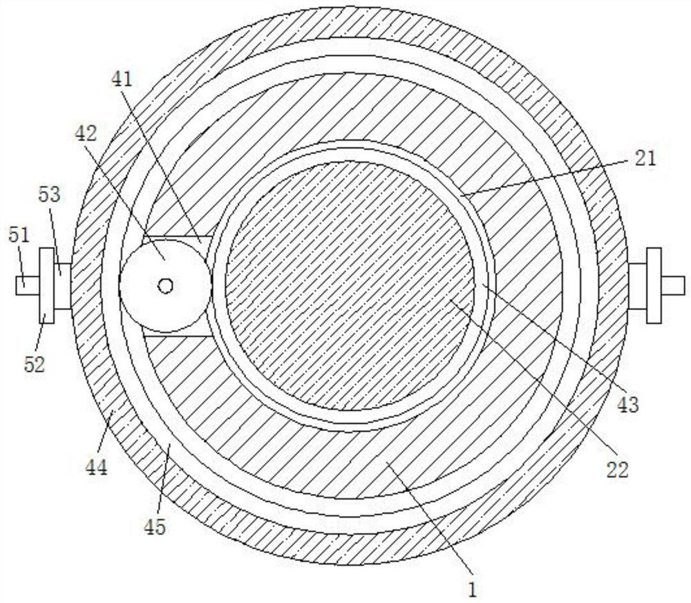
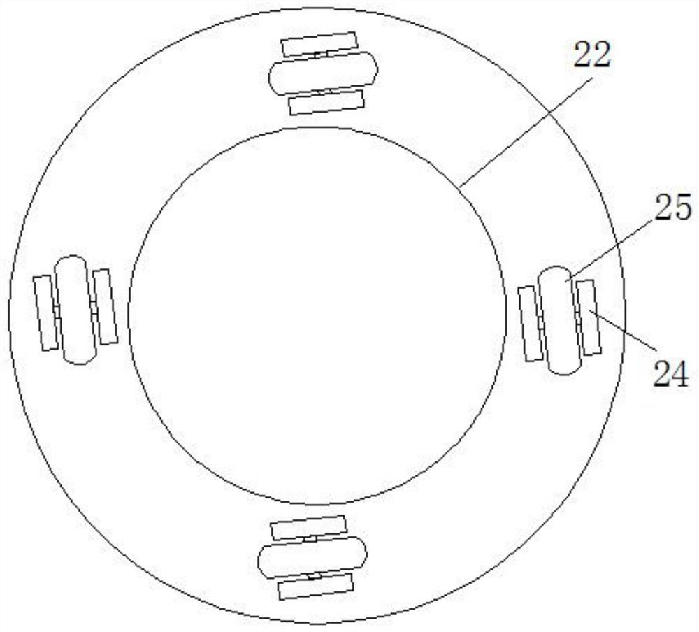
[0031] Embodiment 1: as Figure 1-5 As shown, the specific embodiment adopts the following technical solutions: an angle adjustment structure for monitoring probes, including a fixed seat 1 arranged in a cylindrical shape, a rotating mechanism 2 is arranged at the center of the lower surface of the fixed seat 1, and the rotating mechanism 2 The lower end of the camera is fixedly connected with a camera mechanism 3, a transmission mechanism 4 is arranged on the position corresponding to the rotation mechanism 2 of the fixed seat 1, a cleaning mechanism 5 is installed on the lower end of the transmission mechanism 4, and a lifting mechanism is arranged on the lower surface of the rotation mechanism 2. 6. The lower surface of the rotating mechanism 2 is fixedly connected with an angle adjustment mechanism 7. When in use, the rotating mechanism 2 drives the camera mechanism 3 to rotate to adjust the direction, and at the same time, the transmission mechanism 4 drives the cleaning m...

Embodiment 2

[0040] Embodiment 2: In this embodiment, the cleaning plate 54 in the first embodiment is fixedly installed on the fixed seat 1, and the protective cover 33 is installed on the transmission mechanism 4, and the transmission mechanism 4 drives the protective cover 32 to rotate to The outer side walls of the shield 32 are cleaned.


PUM


Abstract

The invention discloses an angle adjustment structure for a monitoring probe, which comprises a cylindrical fixed seat, a rotating mechanism is arranged at the center of the lower surface of the fixed seat, and a camera mechanism is fixedly connected to the lower end of the rotating mechanism. , the position of the fixed seat corresponding to the rotating mechanism is provided with a transmission mechanism, the beneficial effects of the present invention: a monitoring probe angle adjustment structure of the present invention, when in use, the internal camera is protected by a protective cover and activated The first driving motor drives the rotating block and the camera to rotate, so that the camera is oriented inside the protective cover, and at the same time, the connecting plate is driven to rotate by the transmission between the transmission gear, the first rack, and the second rack, and the connecting plate passes through the first rack. A threaded rod and the fixing plate drive the cleaning plate to rotate, and then clean the outer wall of the protective cover through the cleaning plate, so as to prevent the dust on the outer wall of the protective cover from affecting the monitoring effect of the camera.

Description

Technical field: [0001] The invention belongs to an angle adjustment structure, in particular to an angle adjustment structure for a monitoring probe, and belongs to the technical field of monitoring probes. Background technique: [0002] With the rapid development of science and technology in modern society, surveillance probes commonly known as "electronic eyes" can be seen almost everywhere in cities. For the security and stability of the city and fire prevention and disaster prevention, the monitoring probe has made an indelible positive contribution. [0003] And for example, in the patent application for an angle-adjustable monitoring camera with the patent application number CN201810747576.2, the direction of the monitoring probe is adjusted, and in order to improve its monitoring effect, sometimes its angle needs to be adjusted. , so that it can observe more angles, and when the monitoring probe is monitoring outdoors, its surface will be contaminated with a lot of ...

Claims


Application Information

Patent Timeline
Patent Type & Authority Patents(China)
IPC IPC(8): H04N5/225G03B17/56F16M11/12F16M11/18F16M13/02B08B1/04H04N7/18
CPCG03B17/561F16M11/12F16M11/18F16M13/02H04N7/18H04N23/52H04N23/51B08B1/32
Inventor 渠衍飞
Owner 苏州市相城区渭塘城乡发展有限公司
Learn More