Monitoring device for computer room of internet of things

A computer room and monitoring device technology, applied in the direction of supporting machines, mechanical equipment, machine platforms/supports, etc., can solve the problems of not being able to fully exert the monitoring effect of the camera, small monitoring range, easy to produce monitoring dead angles, etc., to achieve difficult monitoring of dead angles , Large monitoring range, improve the effect of monitoring effect

Pending Publication Date: 2022-07-29
柳州工学院
View PDF1 Cites 0 Cited by
  • Summary
  • Abstract
  • Description
  • Claims
  • Application Information

AI Technical Summary

Problems solved by technology

[0005] The monitoring range of the monitoring device for the above-mentioned computer room is small, and the

Method used


Image

  • Monitoring device for computer room of internet of things
  • Monitoring device for computer room of internet of things
  • Monitoring device for computer room of internet of things

Examples


Example Embodiment

[0046] Example 1:

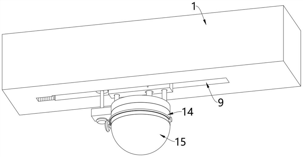
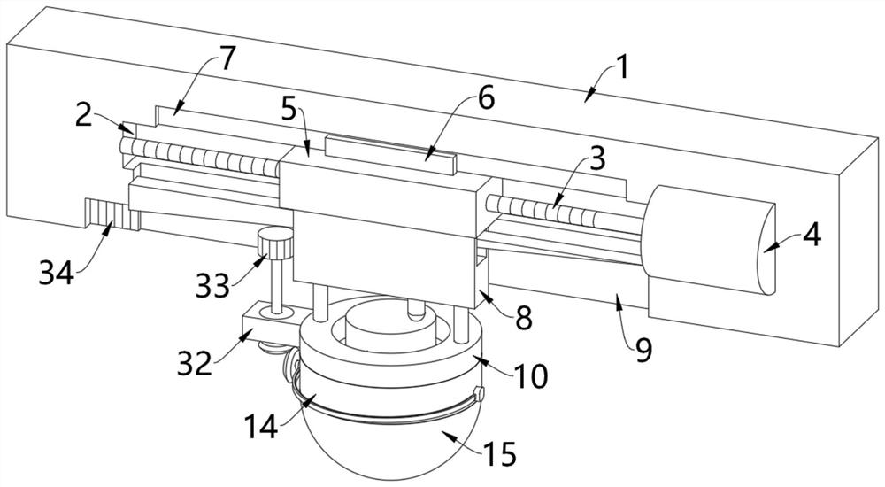
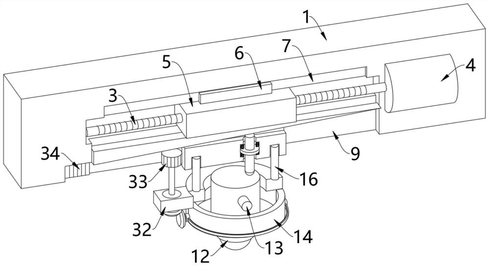
[0047] see figure 1 and figure 2 , The monitoring device for the computer room of the Internet of Things includes an installation cabinet 1, an inner cavity 2 is formed inside the installation cabinet 1, and a screw rod 3 is rotated inside the inner cavity 2, and the screw rod 3 is fixedly installed on the top of the output shaft of the drive motor 4 , the drive motor 4 is fixedly installed in the inner cavity 2;

[0048] The outer wall of the screw rod 3 is threadedly connected with a nut 5, the bottom of the nut 5 is fixedly installed with a connecting plate 8, the connecting plate 8 is movably arranged in the movable groove 9, and the movable groove 9 is opened on the inner bottom wall of the inner cavity 2 to connect The bottom end of the plate 8 extends through the movable groove 9 to the outside of the installation cabinet 1 and is detachably connected with a positioning ring 10 through a connector. The positioning ring 10 is formed with a ring gro...

Example Embodiment

[0052] Embodiment 2:

[0053] see Figure 3-Figure 5 , on the basis of the first embodiment, a slot 18 is horizontally opened on the connecting plate 8, a plug board 19 is inserted in the socket 18, and the two ends of the plug board 19 are fixedly installed on the inner walls of the left and right sides of the movable slot 9 respectively. ,like Figure 4 As shown, the bottom of the plug-in board 19 is an inclined surface, and a movable rod 21 is movably provided between the inclined surface of the bottom of the plug-in board 19 and the right side of the top of the camera 12;

[0054] like Figure 5 As shown, the bottom wall of the slot 18 is provided with a vertical slot 20, the movable rod 21 is movably arranged in the vertical slot 20, the outer wall of the movable rod 21 is fixedly installed with a pressure plate 22, the pressure plate 22 is movably arranged in the plate slot 23, and the plate slot 23 Opened on the side wall of the vertical slot 20, a first spring 24 is...

Example Embodiment

[0059] Embodiment three:

[0060] see Figure 6-Figure 8 , on the basis of Embodiment 1 or Embodiment 2, a bottom cylinder 14 is fixedly installed at the bottom of the positioning ring 10, a glass cover 15 is fixedly installed at the bottom of the bottom cylinder 14, and the silk nut 5 passes through the connecting plate 8, the connecting rod 16 and the positioning The ring 10 drives the camera 12 to move left and right, and the bottom cylinder 14 and the glass cover 15 at the bottom of the positioning ring 10 can protect the camera 12 from dust, block external dust, and prevent the dust from directly adhering to the lens of the camera 12;

[0061] like figure 2 and Image 6 As shown, the left and right sides of the bottom cylinder 14 are rotatably provided with rotating seats 25, and an arc-shaped plate 26 is fixedly connected between the two rotating seats 25. The arc-shaped plate 26 is arranged around the glass cover 15, and the inner wall of the arc-shaped plate 26 is f...


PUM


Abstract

The invention relates to the technical field of monitoring devices, and discloses a monitoring device for an internet of things computer room, which comprises a mounting cabinet, an inner cavity is formed in the mounting cabinet, a screw rod is rotatably arranged in the inner cavity, the screw rod is fixedly mounted at the top of an output shaft of a driving motor, and the driving motor is fixedly mounted in the inner cavity; the outer wall of the lead screw is in threaded connection with a nut, a connecting plate is fixedly installed at the bottom of the nut and movably arranged in a movable groove, and the movable groove is formed in the inner bottom wall of the inner cavity. The driving motor operates to drive the lead screw at the top of the output shaft to rotate, the lead screw rotates to drive the nut in threaded connection with the outer wall of the lead screw to move left and right, the nut moves left and right to drive the camera to move left and right through the connecting plate, the connecting rod and the positioning ring, and the horizontal position of the camera is adjusted. And the camera in dynamic change can obtain a larger monitoring range, so that the monitoring effect is greatly improved, and monitoring dead angles are not easy to generate.

Description

technical field [0001] The invention relates to the technical field of monitoring devices, in particular to a monitoring device for a computer room of the Internet of Things. Background technique [0002] The computer room generally refers to the place where the government or enterprises store servers such as telecommunications, Netcom, mobile, dual-line, electricity, etc. With the rapid development of basic network construction, the number and type of computer rooms are also changing, but so far, most computer rooms are It is still a traditional fixed computer room. For example, network operators mostly use traditional fixed computer rooms to store servers or related processing equipment; in the computer room, in order to realize real-time monitoring of network equipment, monitoring devices are generally used; [0003] For example, the Chinese patent announcement number is: CN108799720A, which provides a computer room monitoring device for the Internet of Things computer, i...

Claims


Application Information

Patent Timeline
IPC IPC(8): F16M11/18F16M11/08H04N5/225H04N5/232H04N7/18
CPCF16M11/18F16M11/08F16M11/045H04N7/18H04N23/51H04N23/50H04N23/695
Inventor 韦灵娄伯韬唐爱龙陈洁珍张藐心
Owner 柳州工学院
Why Eureka
Try Eureka