
A debris flow monitoring device

A technology for monitoring devices and debris flow, which is applied in the direction of measuring devices, measuring instrument components, instruments, etc., can solve the problems of large labor force, lens pollution, troublesome manual processing, etc., and achieve the effects of prolonging the service life, the best monitoring effect, and reducing injuries

Active Publication Date: 2022-08-02
郑爽
View PDF0 Cites 0 Cited by
  • Summary
  • Abstract
  • Description
  • Claims
  • Application Information

AI Technical Summary

Problems solved by technology

[0003] Existing debris flow monitoring devices generally use displacement sensors to measure the moving speed of debris flow, cameras to take pictures of debris flow, and wind detectors to measure the wind force at the debris flow. These devices are placed outdoors. There is a lot of dust, which is easy to pollute the lenses of these devices and affect the accuracy of measurement and shooting. It is troublesome to deal with them manually. At the same time, it needs to be cleaned many times in a short period of time, and the input of labor is relatively large.

Method used


Image

  • A debris flow monitoring device
  • A debris flow monitoring device
  • A debris flow monitoring device

Examples


Embodiment Construction

[0026] The technical solutions in the embodiments of the present invention will be clearly and completely described below with reference to the accompanying drawings in the embodiments of the present invention. Obviously, the described embodiments are only a part of the embodiments of the present invention, but not all of the embodiments.

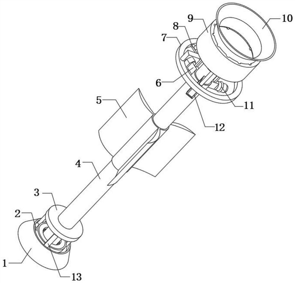
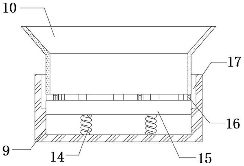
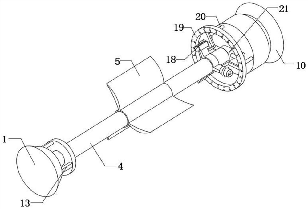
[0027] refer to Figure 1-6 , a debris flow monitoring device, comprising a fixed seat 1 and a restricting frame 9, the bottom inner wall of the restricting frame 9 is fixedly connected with a gravity spring 14 at equal distances, and the top outer walls of a plurality of gravity springs 14 are fixedly connected with the same regulating plate 15 , the outer diameter of the regulating plate 15 is similar to the inner diameter of the restricting frame 9, the top outer wall of the regulating plate 15 is fixedly connected with support rods 16 at equal distances, and the top outer walls of a plurality of supporting rods 16 are fixedly connected w...


PUM


Abstract

The invention belongs to the technical field of debris flow monitoring, in particular to a debris flow monitoring device. For existing debris flow monitoring devices, displacement sensors are generally used to measure the moving speed of debris flow. size, these devices are placed outdoors, the environment in the debris flow is poor, and there is a lot of dust outside, which can easily contaminate the lenses of these devices and affect their measurement and shooting accuracy. It is more troublesome to handle them manually. The following solutions are proposed, including the fixed seat and the restrictor frame. The present invention is provided with grooves, sliding blocks, reset springs and fixed blocks. When the external wind force is large, the fixed rod is driven to rotate by the fan blades, and the reset spring is squeezed. Unload the wind, reduce the long-term damage to the fixed rod caused by the wind, protect the fixed rod and prolong its service life.

Description

technical field [0001] The invention relates to the technical field of debris flow monitoring, in particular to a debris flow monitoring device. Background technique [0002] Debris flow refers to a special torrent that carries a large amount of sediment and rocks due to landslides caused by heavy rain, blizzard or other natural disasters in mountainous areas or other areas with deep ravines and steep terrain; It has the characteristics of large size, large material capacity and strong destructive power. Debris flows often wash away roads, railways and other transportation facilities and even villages and towns, resulting in huge losses. For areas with high debris flow rates, monitoring devices are generally installed there for early prevention. [0003] Existing debris flow monitoring devices generally measure the moving speed of debris flow through displacement sensors, cameras take pictures of debris flow, and wind detectors are used to measure the wind force at the debri...

Claims


Application Information

Patent Timeline
Patent Type & Authority Patents(China)
IPC IPC(8): G01D21/02G01D11/00G01D11/16
CPCG01D21/02G01D11/00G01D11/16
Inventor 郑爽李贝德杨青峰刘行行王国晨韩晓玲董庆龙陈芹成冉冉曹策张志强张学如陈鹏刘文涛张伟朋崔佳星
Owner 郑爽
Learn More