
Combined light-emitting table lamp

A technology for table lamps and components, applied to semiconductor devices, light sources, electric light sources, etc. of light-emitting elements, can solve problems such as high cost, complex structure, and inability to adjust height, and achieve the effect of reasonable structure and increased illuminated area

Inactive Publication Date: 2020-06-02
龚金凤
View PDF0 Cites 0 Cited by
  • Summary
  • Abstract
  • Description
  • Claims
  • Application Information

AI Technical Summary

Problems solved by technology

[0004] In order to overcome the problems that most of the current desk lamps are covered on the lamp by the lampshade to improve the quality of the light, but the structure of the desk lamp is complicated, the cost is high, the height cannot be adjusted, and the mobile phone teacup cannot be placed, the present invention provides a Combined luminous table lamp, the invention utilizes the cooperation of the base, support rod assembly, connecting rod, luminous ring assembly, circuit board, circuit, power supply DC plug, teacup cover and shelf, not only the structure is simple and easy to operate, but also the manufacturing cost is low, It is easy to disassemble, and the teacup cover can be used to place the teacup, which is convenient for people to drink while reading, and the mobile phone can be placed on the shelf, which is convenient for watching videos; multiple support rods are used as support rod components, and the height can be adjusted to suit different groups of people

Method used


Image

  • Combined light-emitting table lamp
  • Combined light-emitting table lamp
  • Combined light-emitting table lamp

Examples


Embodiment Construction

[0038] In order to make the purpose, technical solution and advantages of the present invention clearer, the technical solution of the present invention will be described in detail below. Apparently, the described embodiments are only some of the embodiments of the present invention, but not all of them. Based on the embodiments of the present invention, all other implementations obtained by persons of ordinary skill in the art without making creative efforts fall within the protection scope of the present invention.

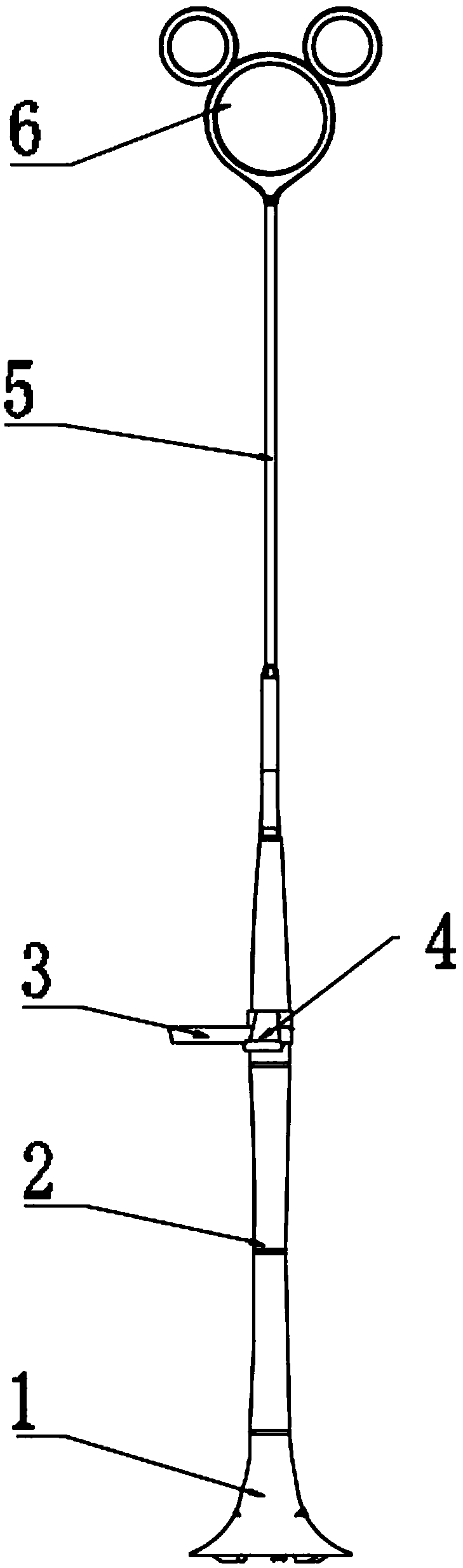
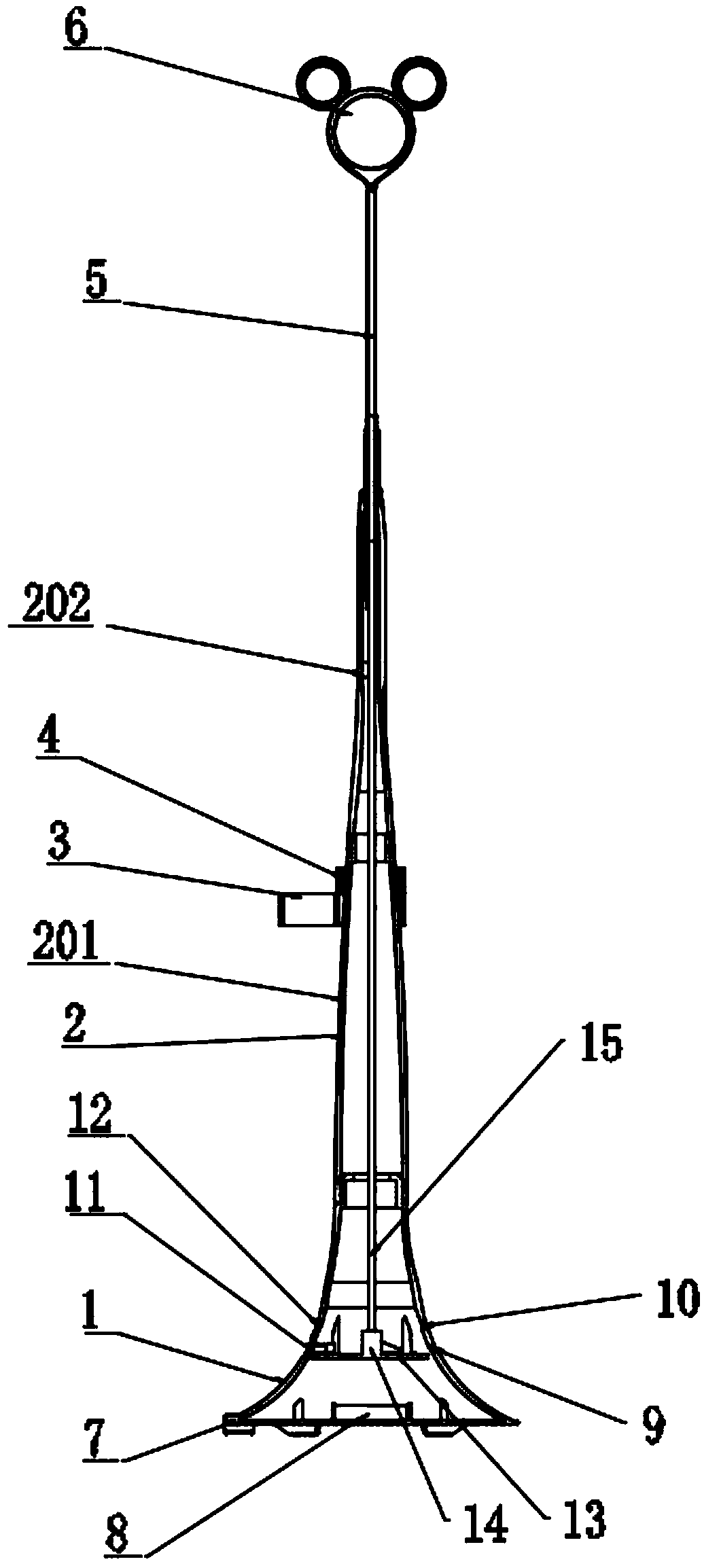
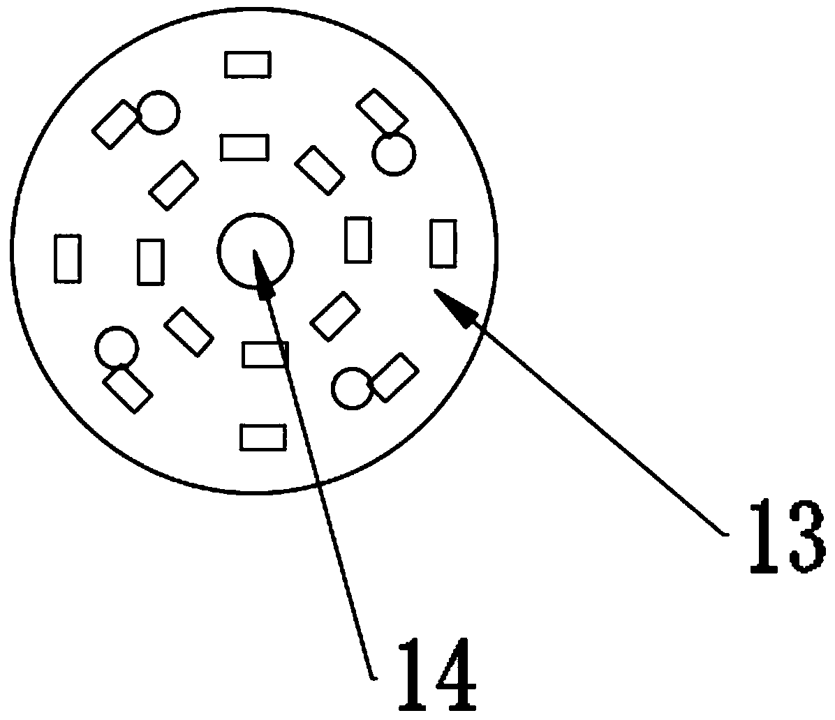
[0039] refer to Figure 1-Figure 3 , the present invention provides a combined light-emitting desk lamp, which includes a base 1, a support rod assembly 2, a connecting rod 5, a light-emitting ring assembly 6, a circuit board 13, a circuit 15, a power supply DC plug 7, a teacup cover 3 and a shelf 4;

[0040] The support rod assembly 2 includes several support rods, and each of the support rods can be detachably connected together;

[0041] The base 1, the sup...


PUM


Abstract

The invention relates to a combined light-emitting table lamp which comprises a base, a supporting rod assembly, a connecting rod, a light-emitting ring assembly, a circuit board, a circuit, a power supply DC plug, a teacup sleeve and a containing frame. The base, the supporting rod assembly, the connecting rod and the light-emitting ring assembly are connected in sequence. The circuit board is detachably mounted in the base; the light-emitting ring assembly is connected with the circuit board through the circuit. The power supply DC plug is electrically connected with the circuit board; and the teacup sleeve and the containing frame are nested on the supporting rod assembly. The table lamp has the advantages that through cooperation of the base, the supporting rod assembly, the connectingrod, the light-emitting ring assembly, the circuit board, the circuit, the power supply DC plug, the teacup sleeve and the containing frame, the structure is simple, operation is convenient, the production and manufacturing cost is low, disassembly is convenient, the teacup sleeve can contain a teacup, and people can drink water conveniently during reading; a mobile phone can be placed on the containing frame to facilitate video watching; a plurality of supporting rods are used as supporting rod assemblies, and the height can be adjusted to adapt to different crowds.

Description

technical field [0001] The invention relates to the field of desk lamps, in particular to a combined light-emitting desk lamp. Background technique [0002] Lamp, lighting supplies, generally refers to appliances that can illuminate. Humans used torches for lighting in ancient times, and later came candles and oil lamps. In ancient times, "candle" was a kind of torch made of flammable materials. The lit torch used to hold it was called a candle; the piles of fine grass and branches placed on the ground to be lit were called liao , Liao placed outside the door is called a big candle, and the one inside the door is called Ting Liao. [0003] Desk lamp, as a kind of lamp, is an indispensable part in life and study. However, most of the current desk lamps are covered with lampshades to improve the quality of light. However, the structure of this desk lamp is complicated, the cost is high, and it cannot be adjusted. Height, and can not place mobile phone cups. Contents of th...

Claims


Application Information

Patent Timeline
IPC IPC(8): F21S6/00F21V21/14F21V17/12F21V19/00F21V33/00F21Y115/10
CPCF21S6/00F21V17/12F21V19/001F21V21/14F21V33/00F21V33/0056F21Y2115/10
Inventor 龚金凤
Owner 龚金凤
Learn More