Multi-connection electric push rod structure

An electric push rod and push rod technology, which is applied in the direction of electric components, electrical components, electromechanical devices, etc., can solve the problems of error, high cost, and connection damage in the synchronization effect, and achieve a large range of deceleration ratio and reduce installation effect of space

Pending Publication Date: 2020-06-02
绍兴市上虞荣达实业有限公司
View PDF0 Cites 0 Cited by
  • Summary
  • Abstract
  • Description
  • Claims
  • Application Information

AI Technical Summary

Problems solved by technology

[0004] The above-mentioned existing technical solutions have the following defects: since each electric push rod is driven by its own drive motor, it is necessary to use a controller to synchronize each drive motor, which is costly, and there will still be errors in the synchronization effect, so that each drive The extension and retraction of the electric push rod are not synchronized, resulting in damage to the connection between the electric push rod and the driven object

Method used


Image

  • Multi-connection electric push rod structure
  • Multi-connection electric push rod structure
  • Multi-connection electric push rod structure

Examples


Embodiment Construction

[0036] The present invention will be described in further detail below in conjunction with the accompanying drawings.

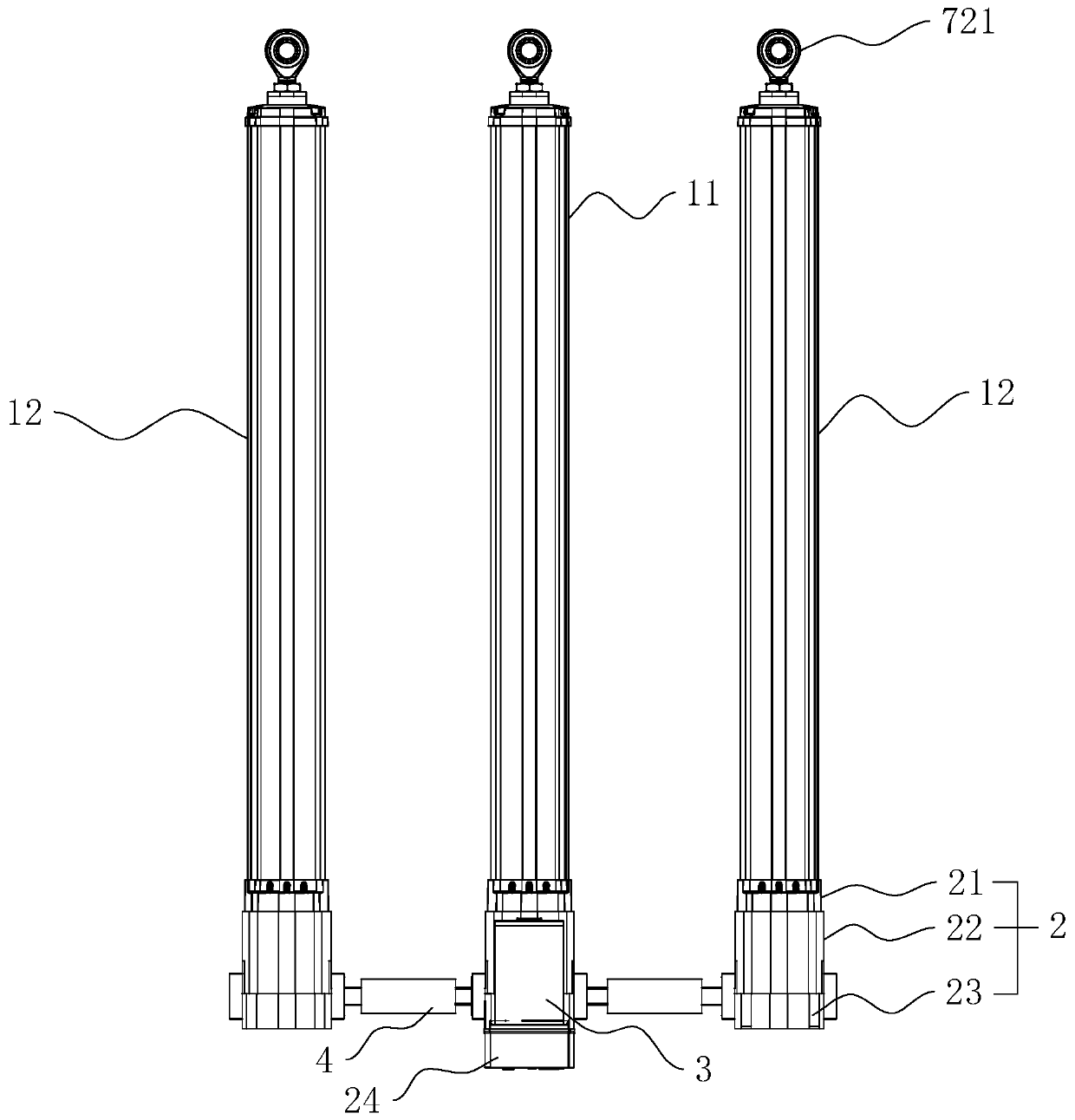
[0037]refer to figure 1 , is a multi-connected electric push rod structure disclosed in the present invention, including a driving push rod unit 11, two driven push rod units 12 respectively located on both sides of the driving push rod unit 11, a driving member 3 and a connecting active push rod unit 11 and the driven push rod unit 12 make the two synchronously retractable linkage 4.

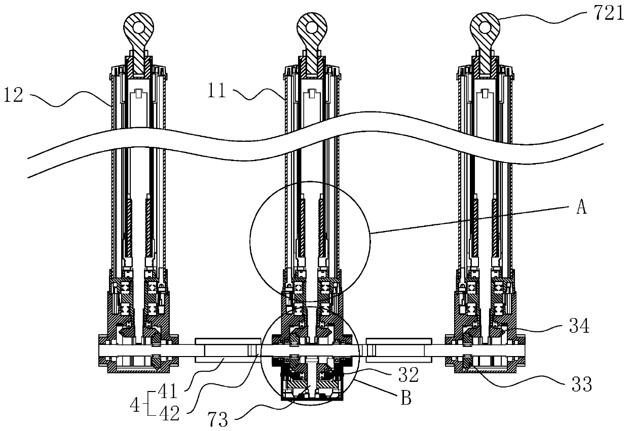
[0038] like figure 1 and figure 2 As shown, the driving member 3 includes a driving motor 31 , a reduction gear set, a first bevel gear 32 , a second bevel gear 33 and a third bevel gear 34 .

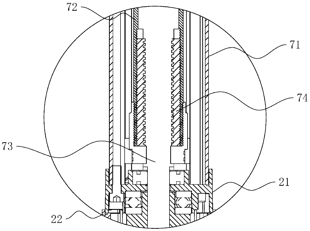
[0039] like figure 1 and image 3 As shown, both the driving push rod unit 11 and the driven push rod unit 12 include a base 2 , an outer tube 71 , an inner tube 72 , a screw rod 73 and a nut 74 .

[0040] like figure 1 and Figure 4 As shown, the base 2 includes a special-shap...


PUM


Abstract

The invention relates to a multi-connection electric push rod structure, which comprises a driving push rod unit, driven electric push rods arranged on the two sides of the driving push rod unit, a driving piece driving the driving push rod unit to stretch out and draw back, and a linkage piece which connects the driving push rod unit and the driven push rod unit so as to enable the driving push rod unit and the driven push rod unit to work synchronously. Each of the driving push rod unit and the driven push rod unit comprises a base, an outer pipe, an inner pipe, a screw and a nut, wherein the screw is rotationally connected to the base; one end of the outer pipe is fixed to the base and arranged outside the screw in a sleeving mode; the inner pipe is arranged in the outer pipe in a penetrating mode and arranged outside the screw in a sleeving mode, the nut is arranged at the end, which faces the base, of the inner pipe and is in threaded connection with the screw; the inner pipe andthe outer pipe are clamped in the rotating direction along the axis; and the driving piece is arranged on the base in the driving push rod unit and connected with the screw to drive the screw to rotate. According to the invention, the electric push rods can be better pushed out and contracted synchronously.

Description

technical field [0001] The invention relates to the technical field of electric push rods, in particular to a multi-connected electric push rod structure. Background technique [0002] Electric push rod, also known as linear drive, is a new type of linear actuator mainly composed of a motor push rod and a control device. The electric push rod includes a base, an outer tube, an inner tube, a screw, a nut and a drive motor. The screw is rotatably connected to the base. One end of the outer tube is fixed on the base and sleeved outside the screw. Set outside the screw, the nut is set on the end of the inner tube facing the base and threadedly connected with the screw, the inner tube and the outer tube are clamped in the direction of rotation along the axis, the driving motor is set on the base and connected with the screw to drive the screw to rotate, When the screw rotates, the inner tube and the nut approach or move away from the base along the axial direction of the screw, ...

Claims


Application Information

Patent Timeline
Patent Type & Authority Applications(China)
IPC IPC(8): H02K7/06H02K7/116F16H37/12F16H25/20F16H57/038
CPCF16H25/20F16H37/124F16H57/038H02K7/06H02K7/116H02K7/1163
Inventor 叶伟青朱稼雨
Owner 绍兴市上虞荣达实业有限公司
Why Eureka
Try Eureka